Define alarms
An alarm is defined on the signal it watches, in the Alarm tab of the Signal properties window. This page sets
two levels on the numeric signal Level_Setpoint: H at 80 and HH at 95. For the meaning of levels, priorities
and acknowledge modes, see How alarms work.
Before you begin
- The signal exists and has been applied. See Create signals.
Define alarms on signals that a field driver reads.
Steps
1. Turn on the alarm feature
Select the signal's row and press Enter to open Signal properties. On the General tab, tick Alarm under Features. The Alarm tab appears; open it.
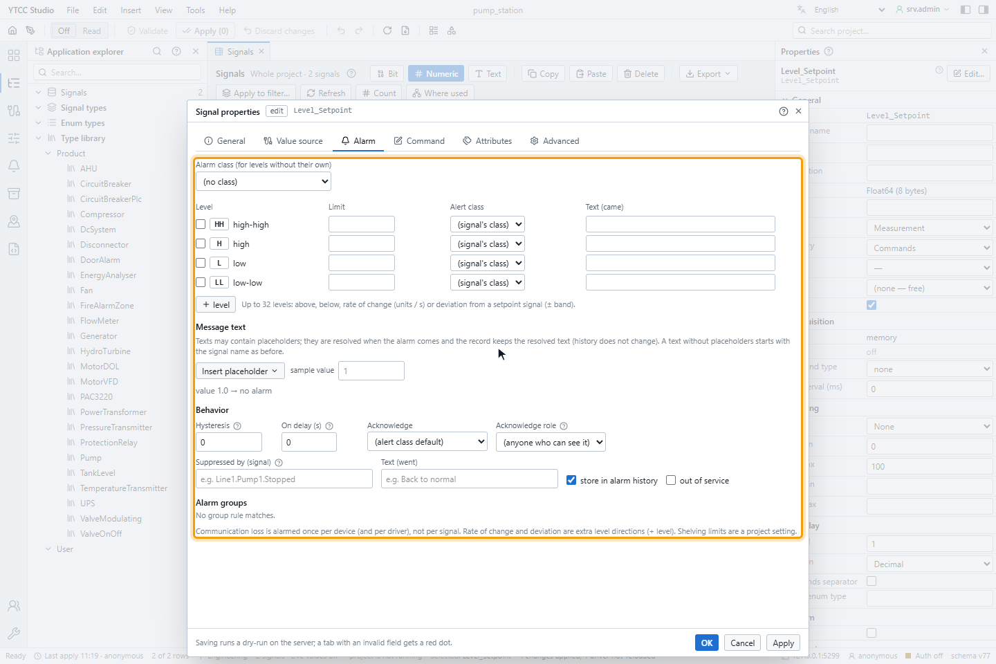
What the tab shows depends on the signal's type: a numeric signal gets levels, a bit signal a state alarm and an integer signal can also have a code alarm. See Bit and integer signals.
2. Set the levels
The table has a row for each fixed level: HH high-high, H high, L low and LL low-low. Tick a level to use it, then fill in:
- Limit — the value at which the level comes, in engineering units. The box stays disabled until the level is ticked.
- Alert class — the class, and so the priority, of this level. (signal's class) uses the class chosen in Alarm class (for levels without their own) above the table.
- Text (came) — the message for this level. Empty uses the signal's message.
For the example, tick H with Limit 80, and HH with Limit 95 and the text Level very high.
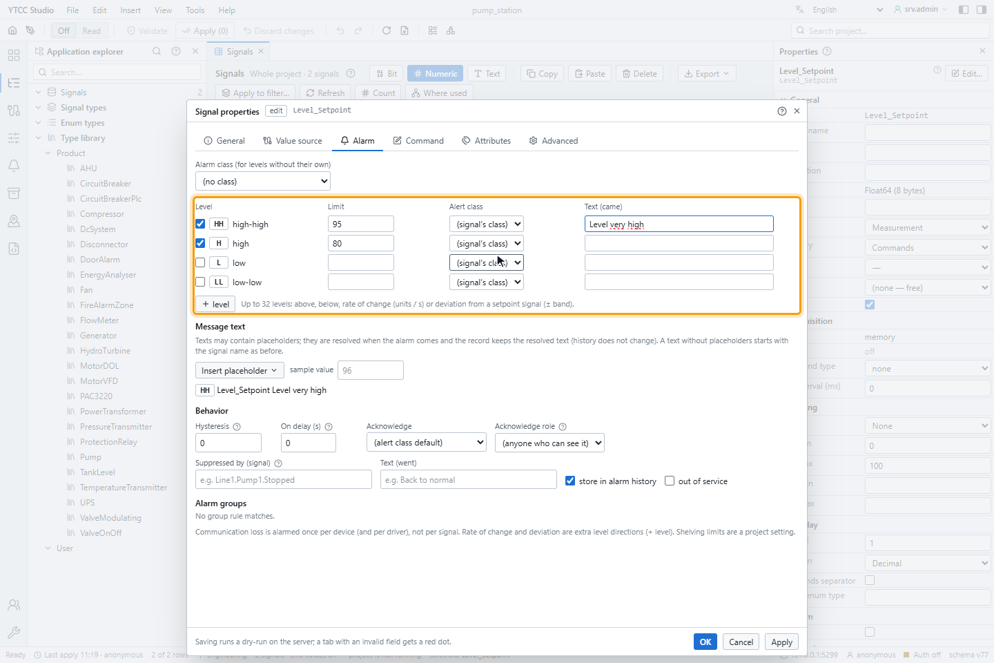
A new project has no alert classes yet, so the lists offer only (signal's class) and (no class). Alert classes are set up in the Alarms work area of the configuration editor, on the Alarm classes tab.
When the value crosses several levels, the most severe one applies, and the alarm changes level instead of opening a second alarm. If its priority rises, for example from H to HH, an acknowledged alarm must be acknowledged again.
3. Add more levels (optional)
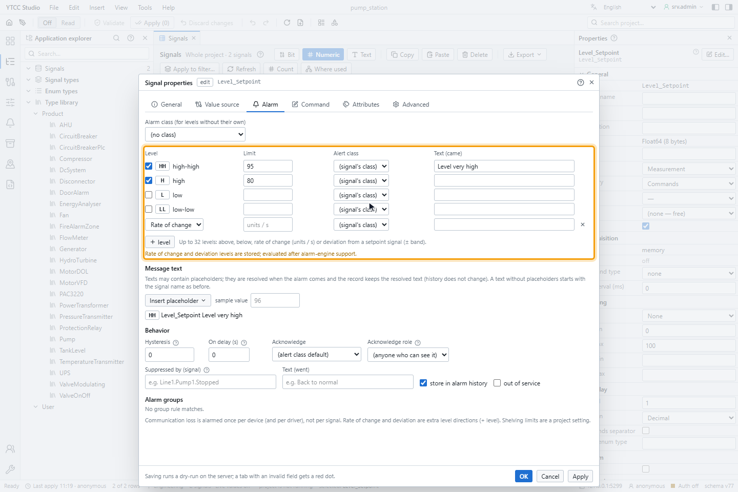
Click + level under the table to add a row. Choose its direction:
| Direction | Limit box |
|---|---|
| Above | The level comes above this value. |
| Below | The level comes below this value. |
| Rate of change | The change per second (units / s) at which the level comes. |
| Deviation from | A setpoint signal and a ± band; the level comes when the value is further than the band from the setpoint. |
A signal can have at most 32 levels, the four fixed ones included; one more shows At most 32 levels. Remove an added row with ×.
4. Write the message text
Each level's Text (came) may contain placeholders. They are filled in when the alarm comes, and the alarm record keeps the filled-in text. A text without placeholders is shown after the signal's name.
Click a text box, then Insert placeholder to add one at the cursor:
| Placeholder | Becomes |
|---|---|
{value} | The value, in the signal's display format |
{unit} | The unit |
{name} | The full path of the signal |
{display} | The display name (the name if it is empty) |
{description} | The description |
{limit} | The limit that was crossed |
{level} | The level (HH, H, L, LL) |
{code} | The code value (code alarm) |
{text} | The code text (code alarm) |
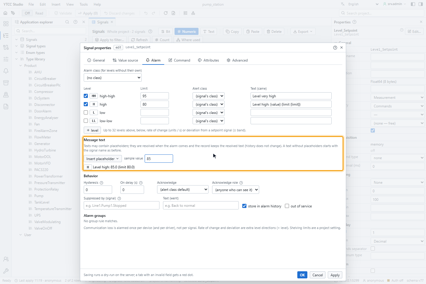
The line under Insert placeholder previews the message: the level, the class and the text for the value in
sample value. Empty uses a value just past the first ticked level. With the text Level high: {value} (limit {limit}) and the sample value 85, the preview reads H Level high: 85.0 (limit 80.0). An unknown placeholder is
shown as unknown placeholder {x}.
5. Set the behavior
The Behavior group applies to all levels of the signal:
| Field | Meaning |
|---|---|
| Hysteresis | The alarm goes only after the value has moved back by this much (engineering units). One value for all levels; 0 is off. With H at 80 and hysteresis 2, the alarm stays until the value is below 78. |
| On delay (s) | The condition must hold this long, without a break, before the alarm comes. If it clears earlier, there is no alarm. The alarm going is always immediate. At most 24 hours. |
| Acknowledge | (alert class default), Not required, When it comes, Came and went separately or Acknowledge removes it. These are the none, came, pair and deletes modes in How alarms work. |
| Acknowledge role | The user role allowed to acknowledge. (anyone who can see it) means anyone who can see the signal's zone. |
| Suppressed by (signal) | While this signal is not 0, the alarm is hidden from the list, the counters and the horn, for example no low-flow alarm while the pump is stopped. It is still evaluated and recorded. |
| Text (went) | The text recorded when the alarm goes, for example Level back to normal. |
| store in alarm history | On by default. Turn it off only for test or nuisance signals; alarm records are part of the audit trail, and switching this off is logged. |
| out of service | Takes the alarm out of service, for maintenance. It is evaluated and recorded but not shown, counted or sounded until you clear the box. |
For the example, set Hysteresis 2, On delay (s) 5, Acknowledge When it comes and Text (went)
Level back to normal.
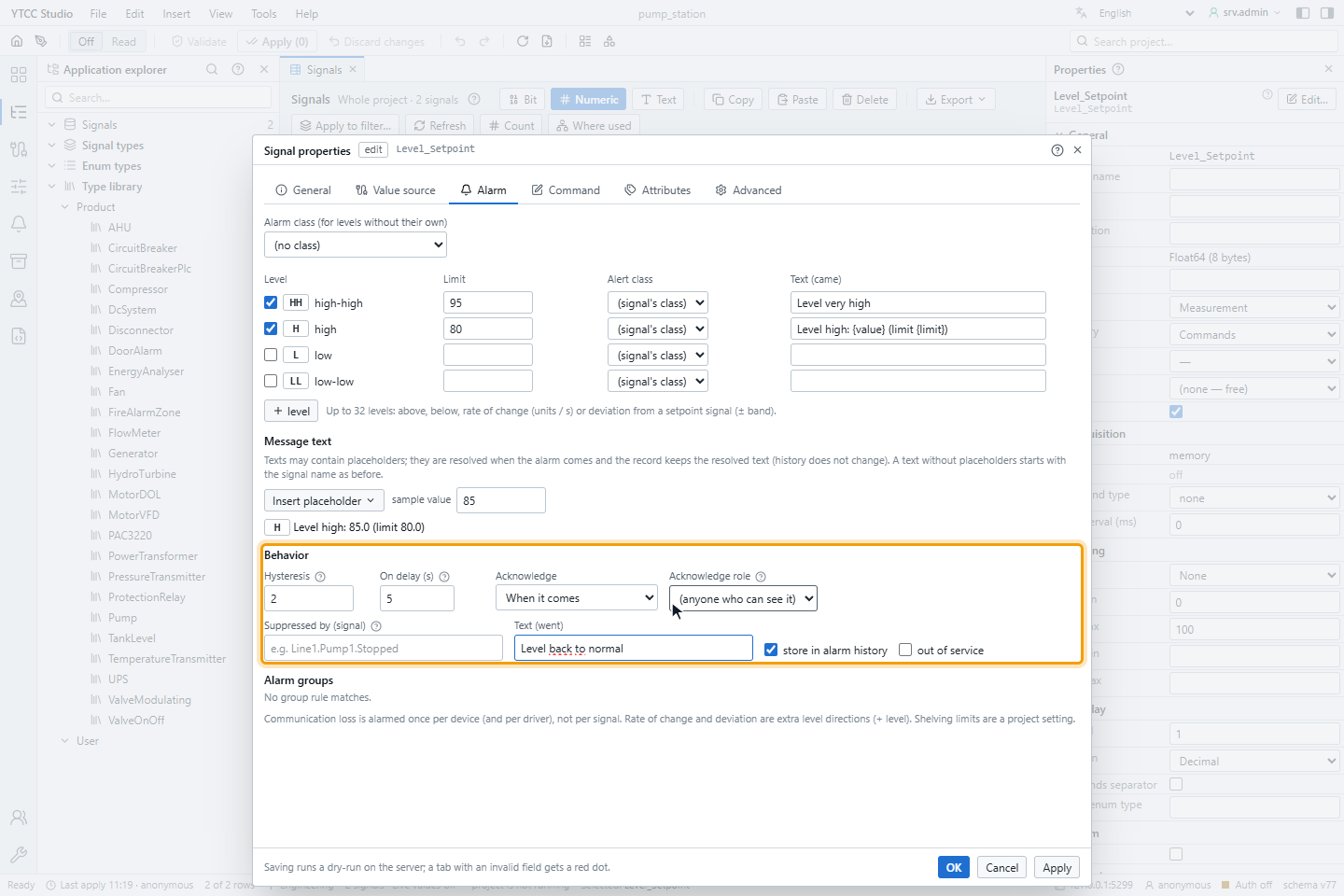
Alarm groups at the bottom lists the group rules that match the signal, or No group rule matches.
6. Save and apply
Click OK, then Apply (n) in the toolbar. Validate changes lists the alarm (point_alarms) and one row for
each level (alarm_ranges), and under Affected drivers the driver that reloads the signal. Click Apply.
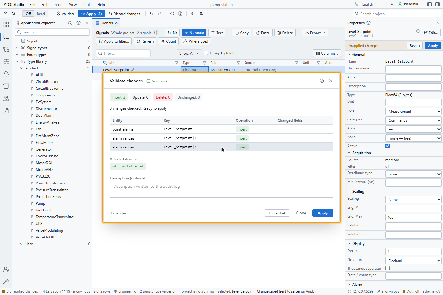
The definition takes effect without a restart: the driver reloads the signal, and the alarm service reads the new definition, within 30 seconds at the latest. Open alarms follow the new text, priority, acknowledge mode and out-of-service setting. If a signal's definition is deleted, its open alarm is closed by the system.
Result
The signal has an alarm with an H and an HH level. Put an Alarm List on a screen to see its alarms when the project runs.
Bit and integer signals
- Bit signals have a state alarm instead of levels. State alarm when is Value is 1 (positive) or Value is 0 (negative), with a Message and an Alert class.
- Integer signals can tick alarm on code (every value other than normal is an alarm). Set the normal code, then choose where the texts come from in texts from: code table, a table with a code, a text and an alert class per row, or enum type, the texts of the signal's enum type. Add a row with + code; remove one with Remove code.
The Message text and Behavior groups are the same for all types.