Process objects
Process objects draw plant equipment and show its state from signals. They are in the SCADA group of the Widgets palette; most open a menu of variants first (see The widget palette). Every value in the State group of the properties can be bound to a signal (see Bind signals).
Before you begin
- A page is open in the screen editor.
Steps
1. Place a tank
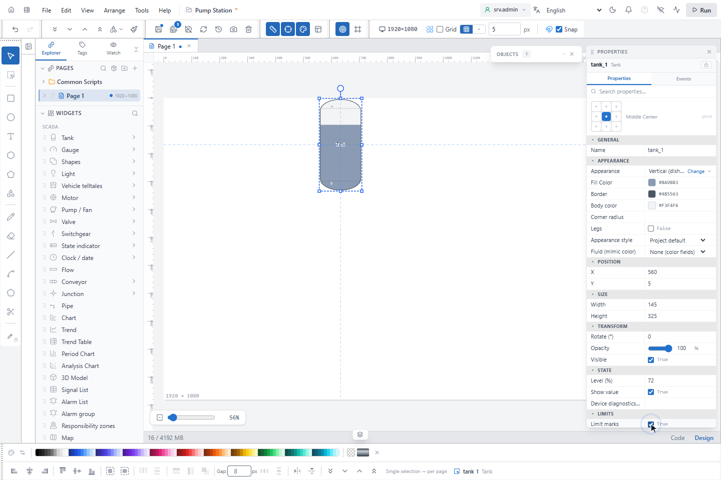
Click Tank, pick a variant (here Vertical (dished heads)) and draw it on the page. Level (%) in the State group sets the liquid (0–100; here 72). Limit marks draws the H and L lines at High limit (%) (90) and Low limit (%) (10); when the level reaches a limit the mark turns Limit exceeded color. In the variant Floating roof, the roof moves with the level.
2. Show the state of a pump
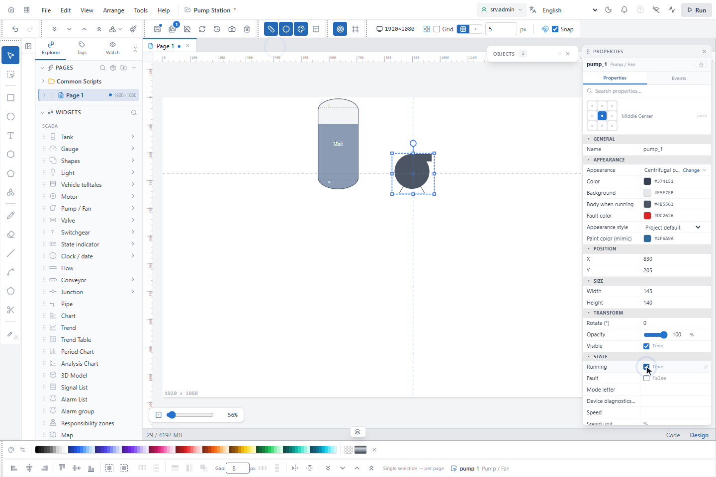
Place a Pump / Fan, here Centrifugal pump. Its State group has Running, Fault, Mode letter
(for example L or R) and Device diagnostics (NE 107). Running draws the body dark (Body when running),
stopped draws it light; a fault draws the outline in Fault color with a ! badge. For a pump or motor on a drive,
bind Speed and turn on Show speed: the speed appears under the symbol with Speed unit (% when empty).
3. Choose the feedback of a valve
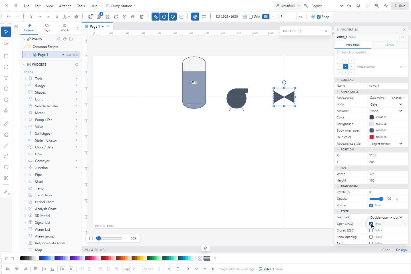
Place a Valve, here Gate valve, and choose Feedback:
| Feedback | Uses | State |
|---|---|---|
| Single (open) | Open (ZSO) | Open or closed |
| Double (open + closed) | Open (ZSO), Closed (ZSC) | Open, closed, travelling (neither) or invalid (both) |
| Opening (%) | Opening (%) | Open above 0.5 % |
An open valve is drawn dark, a closed one light, a travelling one half filled. Body and Actuator change the symbol, and Fail position writes FO, FC, FL or FI next to the actuator. Show opening writes the percentage under the symbol; with Opening (%) feedback, Position bar adds a bar under it.
4. Show the operation state
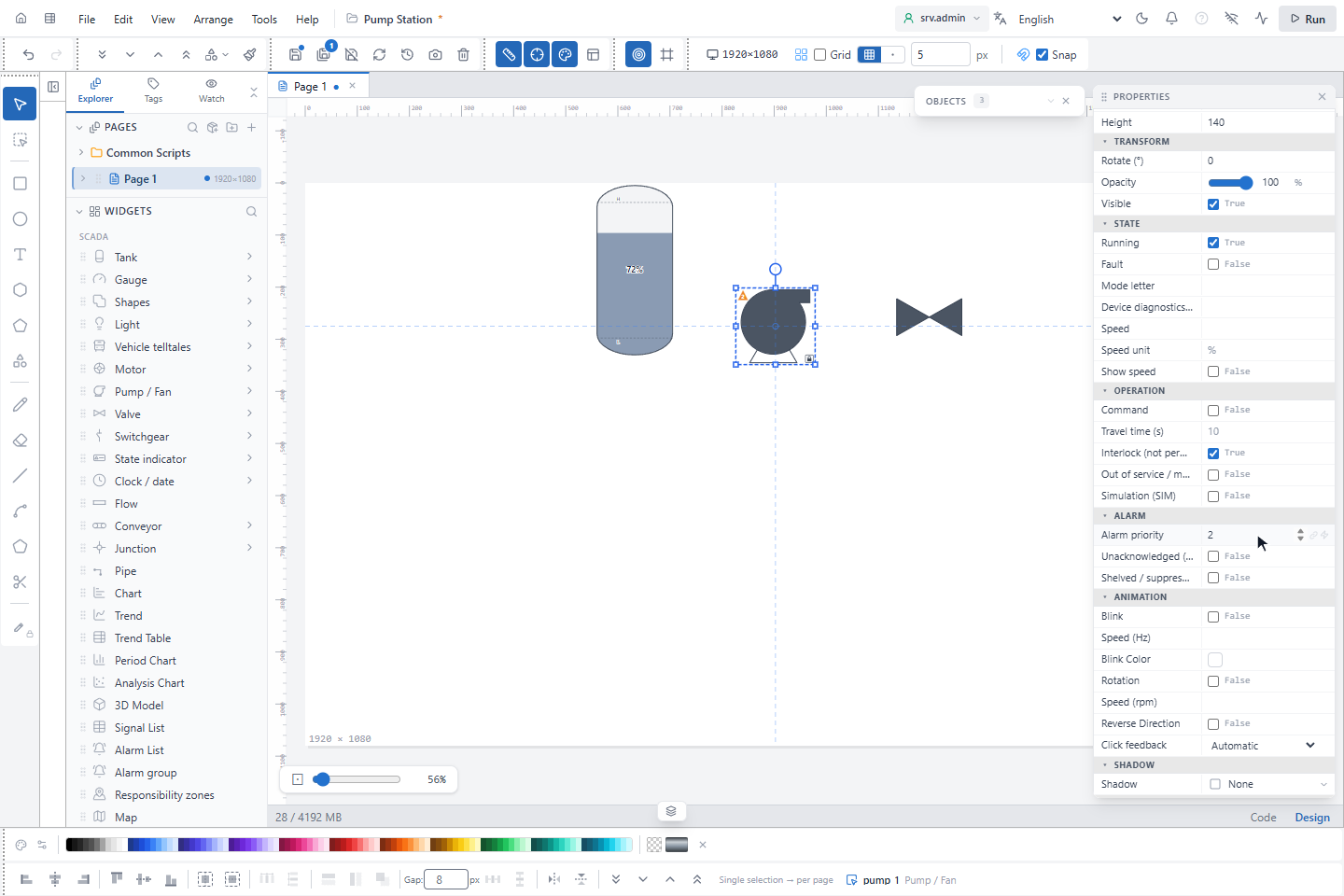
Motors, pumps and valves can show whether a command was carried out and why the equipment does not run. Bind the fields of the Operation group to signals, except Travel time (s), which you type as a number. A field without a value draws nothing.
| Field | Shows |
|---|---|
| Command | The maintained command signal, not a pulse. While it differs from the feedback, the symbol is half filled, without color. |
| Travel time (s) | How long that difference may last; empty means 10 s for a motor or pump and 30 s for a valve. After this time the object shows the alarm color and a ! with the tooltip Discrepancy: the command was not fulfilled in time. |
| Interlock (not permitted) | A padlock |
| Out of service / maintenance | A wrench |
| Simulation (SIM) | The text SIM |
The padlock, wrench and SIM appear at the bottom right, one at a time and without color: Out of service / maintenance
comes first, then Interlock (not permitted), then Simulation (SIM). A valve with Opening (%) feedback has no
Command: Demanded opening (%) takes its place, and a difference above Deadband (%) (default 2) counts in the same
way, with a mark on the Position bar.
The Alarm group draws an alarm mark at the top left, with the shape and number that the alarm list uses:
| Field | Shows |
|---|---|
| Alarm priority | 0 none, 1 a red circle, 2 an orange triangle, 3 a yellow square, 4 a purple diamond; a higher value counts as 4 |
| Unacknowledged (blinks) | The mark blinks |
| Shelved / suppressed | A grey dashed S instead of the priority |
Switchgear has the padlock, wrench and SIM and the Alarm group too, but no Command and no Travel time (s).
5. Connect with pipes
Click Pipe and move near a piece of equipment: its connection ports show as small circles. Click a port to start, click to add corners, and click the port of the next equipment; Enter or a double-click ends the pipe, Esc cancels it. Hold Ctrl for horizontal and vertical segments, Shift for 45°.
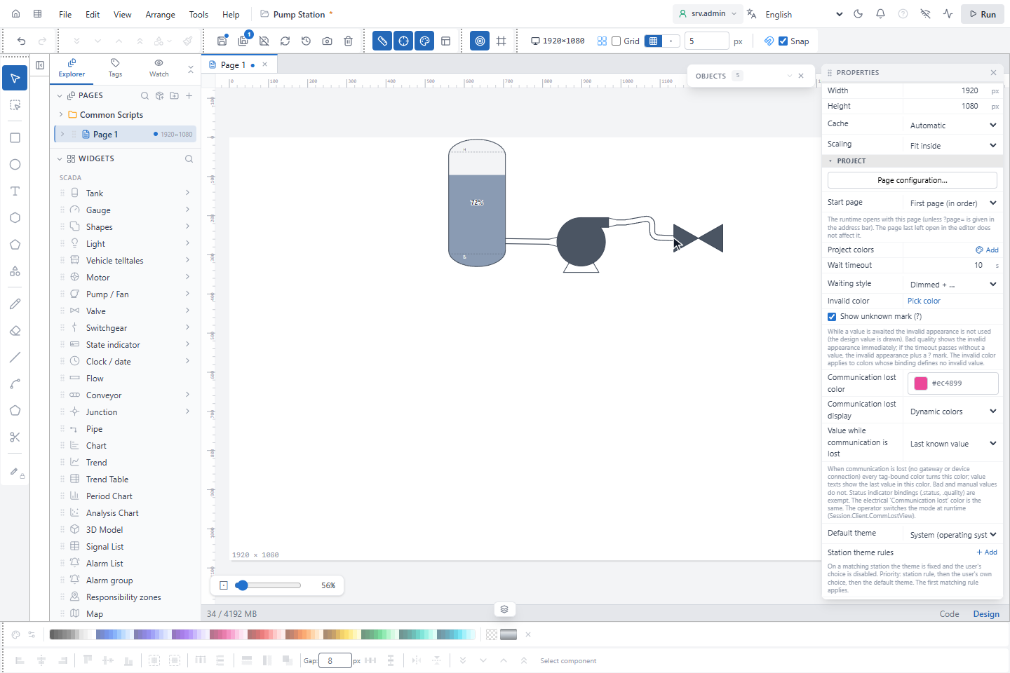
A pipe end snapped to a port stays connected when you move, rotate or resize the equipment. Ending on another pipe makes a branch; a junction joins two to four pipes. Corners are rounded with Elbow Radius (0 = sharp). Flow in the Flow group animates a dashed line along the pipe, with Flow speed and Flow direction.
6. Extend a pipe
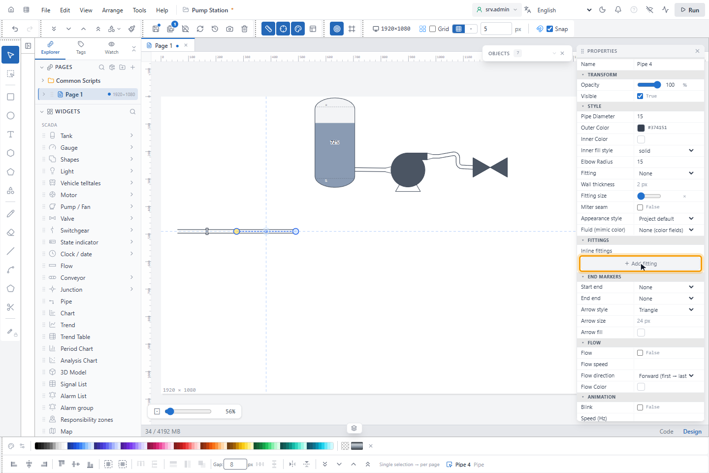
Click Pipe, click the free end of a pipe and draw on. The new part takes the look of that pipe, but never its Inline fittings (group Fittings). The inline fittings also decide what becomes of the two parts:
| The pipe | Result |
|---|---|
| Has no inline fittings | The two parts become one pipe. |
| Has inline fittings | The extension stays a separate pipe. The fittings stay where they are on the first pipe. |
7. Add a junction
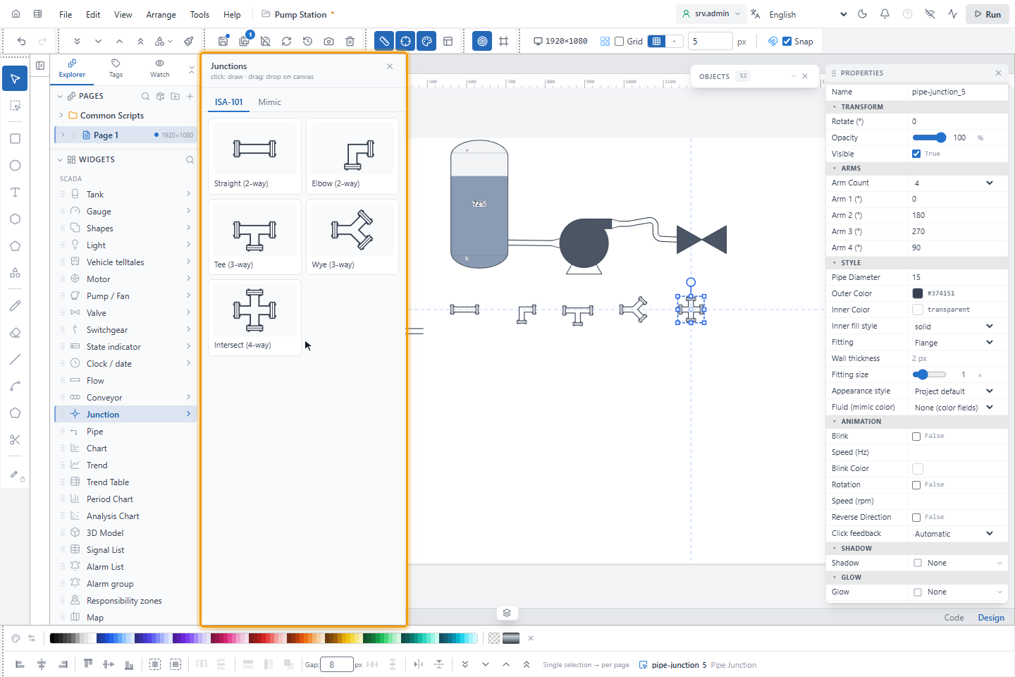
A junction joins two to four pipes. Click Junction: the menu Junctions has the tabs ISA-101 and Mimic and five cards. Click a card and draw it on the page, or drag the card onto the page.
| Card | Arms | Arm angles |
|---|---|---|
| Straight (2-way) | 2 | 0°, 180° |
| Elbow (2-way) | 2 | 0°, 90° |
| Tee (3-way) | 3 | 0°, 180°, 90° |
| Wye (3-way) | 3 | 180°, 315°, 45° |
| Intersect (4-way) | 4 | 0°, 180°, 270°, 90° |
Angles count clockwise from the right, so 90° points down.
8. Connect pipes to a junction
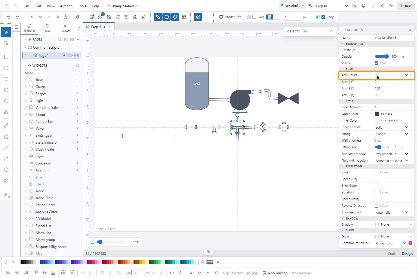
Click Pipe, move to the end of an arm and click: the pipe starts there. A pipe can end on an arm in the same way. Arms do not show the small port circles of equipment. A pipe connected to an arm stays connected when you move the junction.
To change a junction later, use the Arms group: Arm Count and the angle of each arm. A junction has no Appearance row, because a card only sets these values.
9. Choose a conveyor
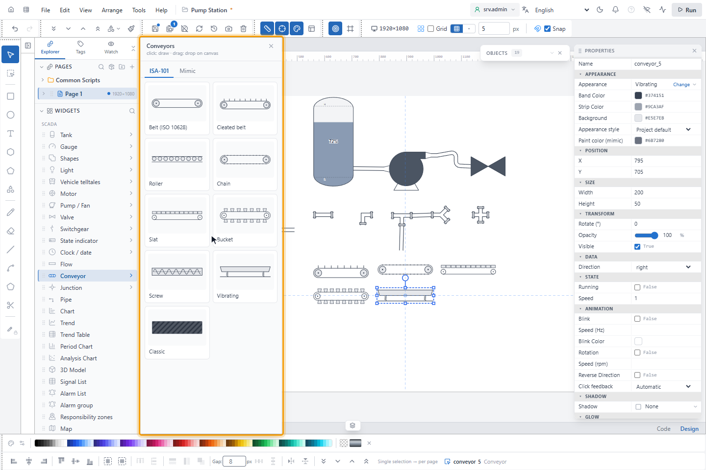
Click Conveyor: the menu Conveyors has the tabs ISA-101 and Mimic and nine cards, Belt (ISO 10628), Cleated belt, Roller, Chain, Slat, Bucket, Screw, Vibrating and Classic. Click a card and draw it on the page. Appearance in the properties shows the variant, and Change replaces it later.
10. Switch to the Mimic style
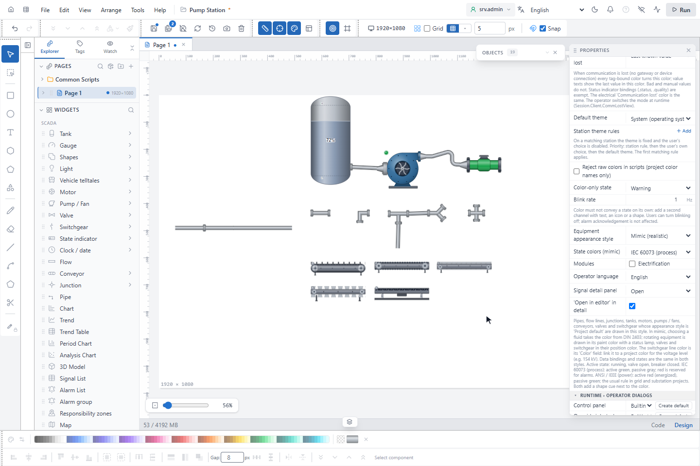
Click an empty part of the page. Under Project, Equipment appearance style sets the style of the whole project: ISA-101 (simple) or Mimic (realistic).
| ISA-101 (simple) | Mimic (realistic) | |
|---|---|---|
| Active state (running, open, closed breaker) | Dark fill | Color from State colors (mimic) |
| Moving parts | Not animated | Impeller, belt and fan turn while running |
| Fluid | Color fields | Fluid (mimic color), DIN 2403 colors (water green, steam red …) |
State colors (mimic) is IEC 60073 (process) (active green, passive grey) or ANSI / IEEE (power) (active red, passive green). A single object can keep its own style: Appearance style in its properties is Project default, ISA-101 (simple) or Mimic (realistic). Bindings and states are the same in both styles.
11. Show a vehicle telltale
A vehicle telltale draws one lamp of a bus, trolleybus or tram dashboard. Click Vehicle telltales in the palette: the menu lists 120 lamps in 11 groups, such as Engine and fuel, Air tanks, Doors, hatches and passengers and Tram. Type in the search box, click a lamp and draw it on the page, or drag the lamp onto the page.
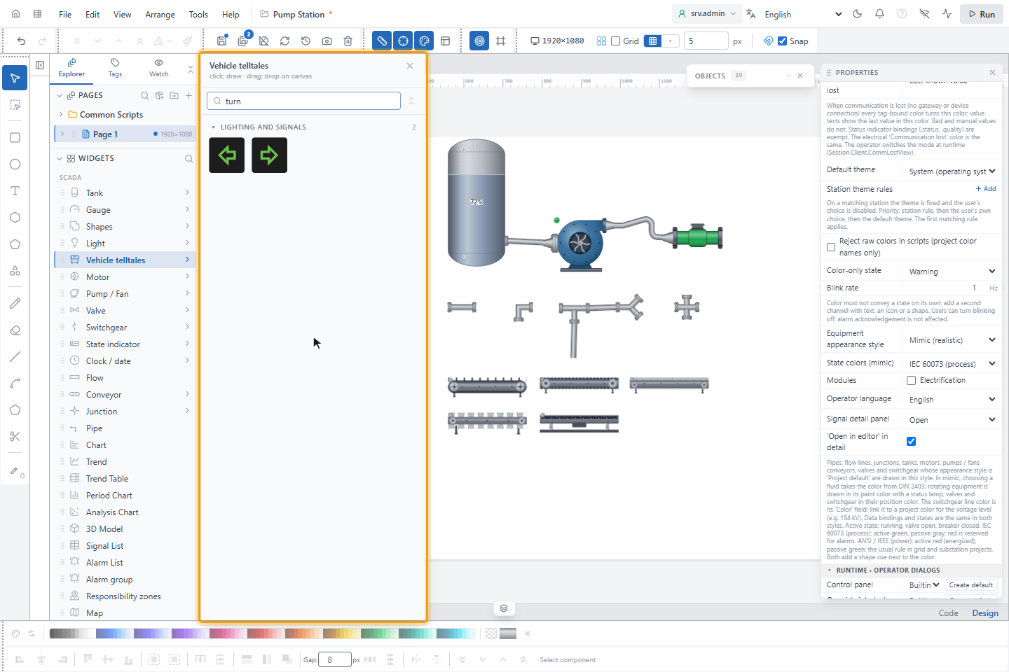
Bind Lit in the State group to a signal; 0 or off turns the lamp off. Flashes makes a lit lamp flash; when it is empty, only the turn signals and the hazard warning flash. Style in the Appearance group is Vehicle panel (dark background) or Lit tile (light background), for a page with a light background. The lit color comes from the icon: red for danger, amber or yellow for caution, green for running, blue for high beam and white for information. While its value has not arrived, the lamp is never shown lit. All settings: Vehicle telltale.
Other process objects
| Object | Main settings |
|---|---|
| Gauge | Value, Min, Max, color zones, Normal low / Normal high, Setpoint (SP); Zone color Always or only while the value is inside (ISA-101); Value position Center, Lower or, on a bar gauge, at the marker: the value sits in a box that moves with the value |
| Light | Lit, Color, Off color |
| Motor | Running, Speed (rpm) (only the turning speed of the symbol), Symbol letter |
| Switchgear | Position (double point): 0 intermediate, 1 open, 2 closed, 3 invalid; Fault, Mode letter (L / R) |
| Conveyor | Running, Speed (only the speed of the belt animation), Direction |
| Flow | A straight flow line: Flow, Speed, Pipe Color, Flow Color |
All settings: Tank, Gauge, Light, Motor, Pump / Fan, Valve, Switchgear, Conveyor, Pipe, Pipe Junction.
Good to know
- While a bound value has not arrived the object is grey and dashed; it never shows a state it does not know.
- Color alone does not carry a state in ISA-101: the active state is a dark fill and color is kept for abnormal states.