S7 (S7comm)
The S7 driver reads and writes data blocks, flags, inputs and outputs of Siemens S7-300, S7-400, S7-1200 and S7-1500 PLCs over S7comm (ISO-on-TCP). For what all drivers have in common, see How drivers work.
Protocol and role
| Role | Client. YTCC connects to the PLCs. |
| Transport | ISO-on-TCP (RFC 1006), classic S7comm |
| Default port | 102 |
| Devices per driver | Any number; each PLC has its own connection. |
| Driver type | S7 (s7) |
The driver uses classic S7comm. The PLC must allow classic access.
What the PLC needs
- S7-1200 and S7-1500: in the CPU properties, under Protection & Security › Connection mechanisms, tick Permit access with PUT/GET communication from remote partner.
- Data blocks: turn Optimized block access off for every data block that YTCC reads or writes, and use absolute addresses (offsets) from the block.
- Rack and slot: S7-1200 and S7-1500 normally use rack 0, slot 1; S7-300 and S7-400 normally rack 0, slot 2.
Device parameters
Set these on the device in Drivers → devices (see Add drivers and devices). An empty box uses the default shown in it.
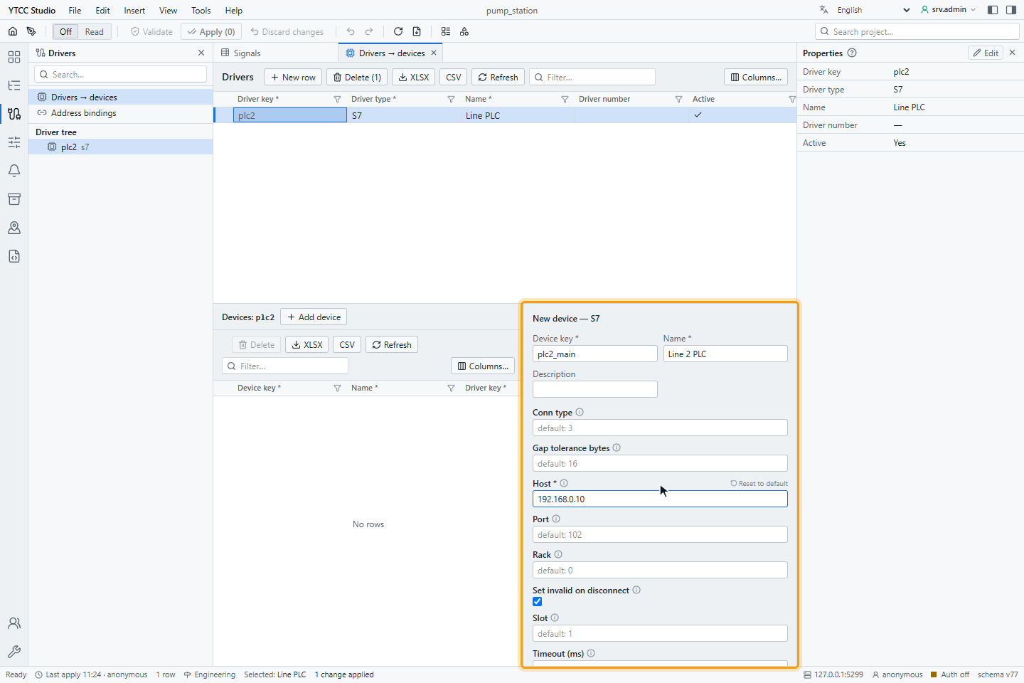
| Parameter | Default | Range | Meaning |
|---|---|---|---|
| Host | — (required) | IP address or host name | Address of the PLC. |
| Port | 102 | 1–65535 | ISO-on-TCP port. |
| Rack | 0 | 0–255 | Rack number of the CPU. |
| Slot | 1 | 0–255 | Slot number of the CPU. |
| Conn type | 3 | 1, 2, 3 | Connection type the PLC sees: 1 PG (programming device), 2 OP (operator panel), 3 S7 basic. |
| Timeout (ms) | 1000 | 1 and more | How long the driver waits when it connects and for each read or write. |
| Gap tolerance bytes | 16 | 0–65535 | How many unused bytes may lie between two signals before the driver reads them in separate requests. |
| Set invalid on disconnect | on | on / off | When the connection is lost, mark all signals of the PLC as Bad · Not connected. When off, the signals keep their last value and quality. |
Changing Host, Port, Rack, Slot, Conn type, Timeout (ms) or Set invalid on disconnect reconnects that PLC. Changing Gap tolerance bytes or a signal address takes effect without dropping the connection. A PLC with an invalid setting does not connect and shows the reason; the other PLCs of the driver keep running.
Signal address
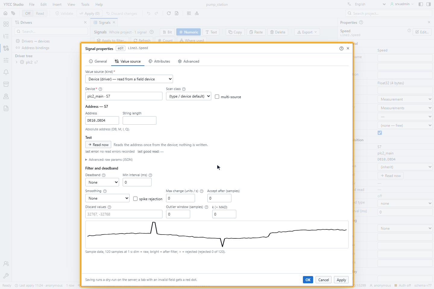
Set the address on the Value source tab of the signal, under Address — S7. The same syntax is used in import files (see Import and export with Excel or CSV). Spaces are removed and the address is stored in upper case.
| Area | Bit | Byte | Word (2 bytes) | Double word (4 bytes) |
|---|---|---|---|---|
| Data block | DB10.DBX4.3 | DB10.DBB4 | DB10.DBW4 | DB10.DBD4 |
| Flags (memory) | M10.0 | MB10 | MW10 | MD10 |
| Inputs | I0.1 (or E0.1) | IB0 | IW0 | ID0 |
| Outputs | Q0.0 (or A0.0) | QB0 | QW0 | QD0 |
The byte number is the offset in the area; the bit number is 0–7.
Data types
The address width decides the type:
| Address | S7 type | Value in YTCC |
|---|---|---|
Bit (DBX, M10.0 …) | BOOL | On or off |
Byte (DBB, MB …) | BYTE | Unsigned number 0–255 |
Word (DBW, MW …) | INT | Signed 16-bit integer |
Double word (DBD, MD …) | REAL | 32-bit floating-point number |
For another type, add "s7_type" in Advanced: raw
params (JSON), for example {"s7_type": "dint"}. The types are bool, byte, sint, char, word, int,
dword, dint, real, lreal, lint, ulint, lword, string, wchar and wstring. A string or wstring
also needs String length: up to 220 characters for string and 109 for wstring.
S7 values are big-endian. A scale and offset set on the signal are applied after reading, and Filter and deadband works as for every driver.
Reading
The driver polls. It groups the signals of a PLC by area, data block and scan period, and reads neighbouring bytes in one request, as long as no gap is larger than Gap tolerance bytes and the request fits the PLC's PDU. When the connection opens, it reads every block once; then each block is read at the period of its scan class (see How often values are read). Each PLC is read one request at a time.
If a request fails because of one bad address, the driver splits it until it finds that address. The bad signal is Bad; the others are read normally.
Writing
A signal can be written when its Access is Read / Write or Write only. All types above can be written; a bit is written without changing the other bits of the byte, and text is padded to its declared length.
- If the PLC is not connected, the command is rejected at once. A command waiting when the connection drops is cancelled, not sent later.
- Each PLC accepts up to 4 waiting commands; more are rejected as Previous command in progress.
- If the PLC refuses the item, for example because PUT/GET is off, the command is rejected with Device returned an error.
- If the signal is set to read back after writing, the driver reads the address again right after a successful write.
For how operators send and confirm commands, see Send commands.
Quality mapping
| Situation | Quality of the signals |
|---|---|
| Read succeeded | Good |
| The PLC refuses the item (return code 01, 03, 05, 06, 07, 0A) | Bad for that signal; the connection stays up |
| The value cannot be converted | The signal is not updated; the error is logged |
| Timeout, connection error | The connection is closed and opened again; with Set invalid on disconnect, all signals of the PLC are Bad · Not connected |
Read the value together with its quality. Do not use a value whose quality is Bad or Bad · Not connected.
Reconnecting
The S7 driver uses its own reconnect timing: it tries again after 50 ms and doubles the wait up to 5 seconds, without a limit on the number of attempts. A PLC that is switched on later is connected within about 5 seconds.
Time stamps
S7 does not carry the time of a value. The time a value arrives in YTCC is used for both time stamps.
Diagnostics
Read now on the Value source tab reads the address once and shows the result or the error:
| Text | Meaning |
|---|---|
| S7 item error 0x03 — Access to object not allowed | PUT/GET is not permitted, or the area is protected |
| S7 item error 0x05 — Address out of range | The offset is beyond the end of the data block |
| S7 item error 0x0A — Object does not exist | The data block does not exist, or it has optimized block access |
| Not connected — … was not read | The PLC is not connected |
| Timeout — no response from … within … ms | The PLC does not answer within Timeout (ms) |
| Invalid S7 address '…' | The address cannot be parsed |
| Symptom | Likely cause |
|---|---|
| All signals Bad · Not connected, the device does not connect | Wrong host, port, rack, slot or connection type; PLC off; firewall |
| One signal Bad, the others good | Wrong data block or offset, or optimized block access on that block |
| All signals of an S7-1200/1500 Bad although connected | PUT/GET not permitted |
| Value looks wrong | Wrong type for the address; set s7_type in raw params |
| Command rejected with Signal not found | The signal is not writable; set Access to rw on the signal |
The communication alarm and the device status work as for every driver; see How drivers work.
Supported functions
| Function | Supported |
|---|---|
| Connection set-up (COTP, S7 setup communication) | Yes |
| Read variable, one item per request | Yes |
| Write variable, one item per request (bit writes included) | Yes |
| Areas DB, M, I, Q | Yes |
| Types BOOL, BYTE, SINT, CHAR, WORD, INT, DWORD, DINT, REAL, LREAL, LINT, ULINT, LWORD, STRING, WCHAR, WSTRING | Yes |