How the live single-line diagram works
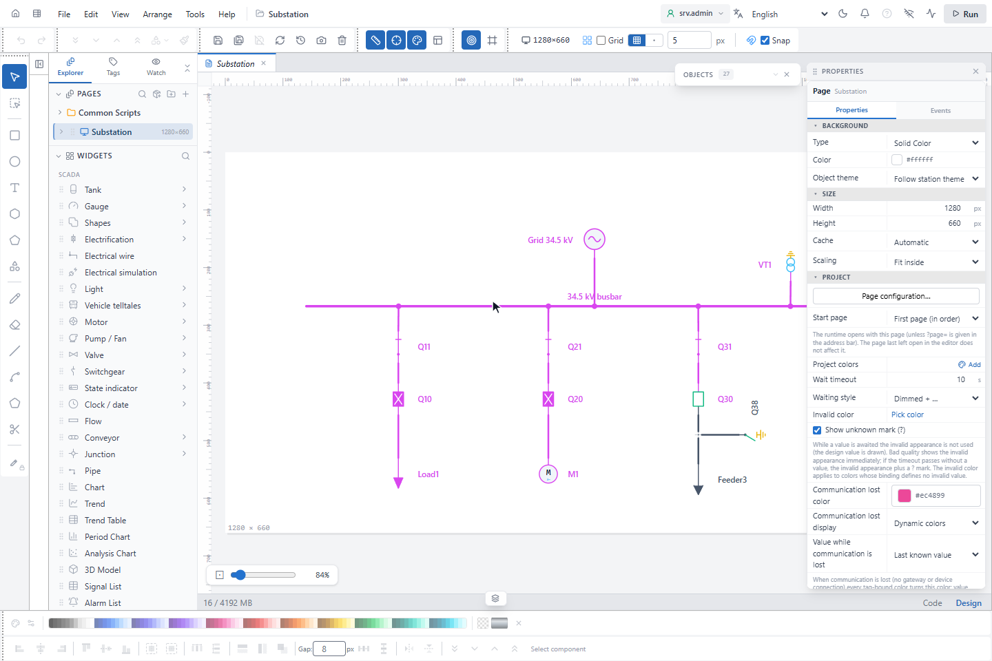
A single-line diagram in YTCC is drawn with electrical symbols and wires in the screen editor. You do not color the lines yourself: YTCC follows the network from each source through the closed switches and colors every section by what reaches it. When a breaker opens, everything below it turns de-energized at once, on every screen.
Sections and sources
The diagram is split at every switch into sections: the busbar, a feeder cable between two switches, the winding side of a transformer. A section gets the color of the source that reaches it through switches that are closed.
- A source symbol (grid supply, generator, PV, wind turbine…) feeds the source chosen for it, for example 34.5 kV. Each source belongs to a voltage level, and the level gives the color.
- A transformer passes energy to its other side and gives that side the source set on the transformer. Fed from below, it gives the upper side the Reverse feed source; with no reverse feed source it does not pass energy upwards.
- A section that no source reaches is de-energized (grey). An earthing switch that is closed makes its section earthed (yellow, dashed).
How to set levels and sources: Voltage levels, sources and palette.
Definite and possible
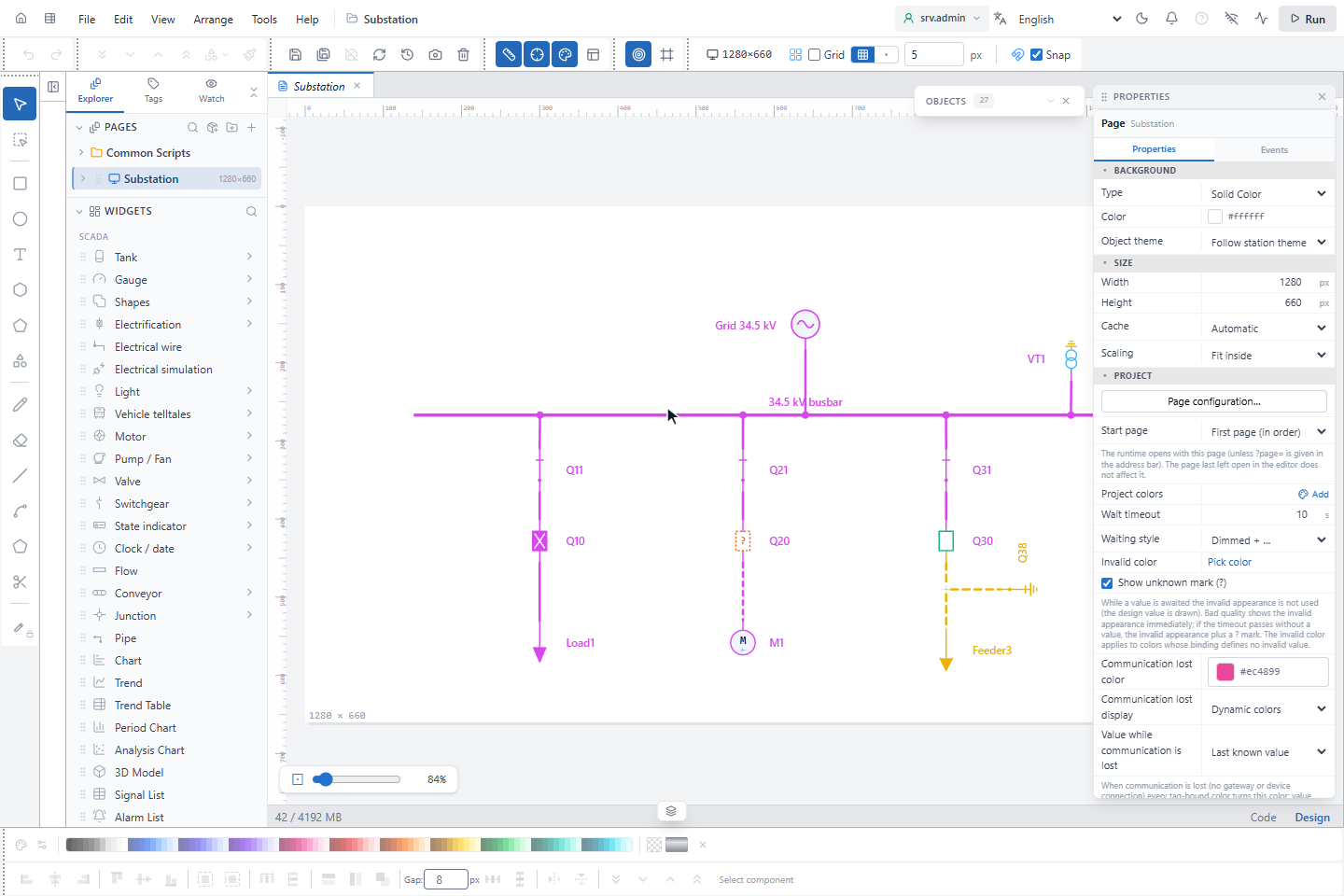
A switch whose position is not known for certain may be closed or open: an intermediate or invalid position, a bad value or a value that never arrived. YTCC does not hide this; it shows each section on one of three levels:
| Level | When | Drawn |
|---|---|---|
| Definitely energized | A path from the source reaches the section through switches that are closed for certain. | Solid, in the level color |
| Possibly energized | The path passes a switch whose position is not certain. | Dashed, in the level color |
| Possibly de-energized | The path passes only a switch whose last known position was open, or a measurement says "no voltage" but the topology is not certain. | Dashed, in the de-energized color |
The switch itself shows the reason: an intermediate position is an orange blinking ?, an unknown value a grey ?.
For safety decisions a possible state counts as a definite one. A possibly energized section cannot be earthed, and the interlocks treat it as live.
Conflicts
A section is in conflict when two states that cannot exist together meet in it:
- energized and earthed (a short circuit),
- two different networks (two sources whose level is not marked Parallel),
- two different voltage levels (a different nominal voltage, or AC and DC).
| Kind | When | Drawn |
|---|---|---|
| Definite conflict | Both sides are certain | Red, blinking |
| Possible conflict | At least one side is possible | Amber, dashed, steady |
The tooltip of a possible conflict names the sources, for example Possible conflict: 154 kV ↔ 34.5 kV (position not certain). A possible conflict does not blink: it may disappear by itself once the position is known.
Measurements
A voltage measurement on a busbar, a VT or a switch checks the topology against the real voltage. Only voltage is used as proof of energy, not current. The measurement point shows a small U badge in the color of its result.
- A measurement that shows voltage turns a possibly energized section into a definitely energized one.
- "No voltage" alone never proves a dead section; earthing stays blocked until the topology is also certain.
- When topology and measurement disagree for longer than the Mismatch delay (s) (5 s by default), the badge turns into ⚠ and blinks, with a tooltip such as Topology energised, measurement shows no voltage — check the VT / measurement or the position information. The delay keeps a normal switching operation, where position and voltage update at different moments, from raising a warning.
How to connect measurements: Bind signals to electrical symbols.
What blinks
Only states that need attention blink, all on one clock and in step. The rate is a project setting, 1 Hz by default and 3 Hz at most.
| Blinks | Steady |
|---|---|
| Definite conflict | Possible conflict |
| Short circuit and earth fault zones | Communication lost (pink, last known position) |
| Measurement mismatch (after the delay) | Possibly energized or de-energized (dashed) |
| Trip, intermediate position, blown fuse | Residual voltage mark, grey ? |
| Join warning badge, what-if preview |
If the theme or the accessibility settings turn blinking off, nothing blinks.
Communication lost
When a signal has no connection (the gateway or the driver is disconnected), YTCC keeps its last value and marks it as communication lost (pink) instead of discarding it. A bad value, or one that never arrived, counts as unknown (grey ?).
| View | Symbol | Network |
|---|---|---|
| Last known position (default) | Drawn in its last position, with a pink lower half or frame | Last known closed → possibly energized; last known open → possibly de-energized |
| Unknown | Position hidden, grey ? | Possibly energized |
Communication lost is information that is missing, not an alarm, so it does not blink. The operator can switch the view on the run screen; see Voltage levels, sources and palette. Commands are not sent to a device without communication.
Where the colors are calculated
With Coloring source set to Server (recommended), the topology service on the server calculates the states once for all screens. Every screen shows the same result, and it matches the topology alarms. A screen calculates by itself when:
- no result arrived within 3 seconds after the page opened,
- the topology service has not reported for 15 seconds or is not ready,
- the connection to the server is lost (symbols then show the communication lost view),
- the page differs from the one the service knows, for example right after it was edited.
The switch is seamless: both calculations use the same rules, so the colors do not change. The screen editor and the preview always calculate locally. With Local (this screen computes), every screen always calculates by itself; use it only where the topology service is not installed.
The topology service runs only for a project whose Modules › Electrification is ticked in the page properties; see Place symbols and draw wires. After changing it, restart the project.
Interlocks are checked with the values at the moment of the command, whichever coloring source is used.