Check and simulate a diagram
Before you run a single-line diagram with live values, check that it is connected correctly and try it: the electrical check lists what is missing, and the electrical simulation lets you open and close switches in the editor and see the colors and interlocks react. Simulated values are never written anywhere.
Before you begin
- A page with an electrical diagram is open in the screen editor. See Place symbols and draw wires.
- The project's Electrification module is on: click an empty place on the canvas and, in PROPERTIES under PROJECT, tick Modules › Electrification. A new project has it off. After changing it, save and restart the project; see Place symbols and draw wires.
Steps
1. Go to a finding
The ELECTRICAL CHECK section of the Explorer lists the findings of the open page, errors first, then warnings and information. Click a row: the object is selected on the canvas.
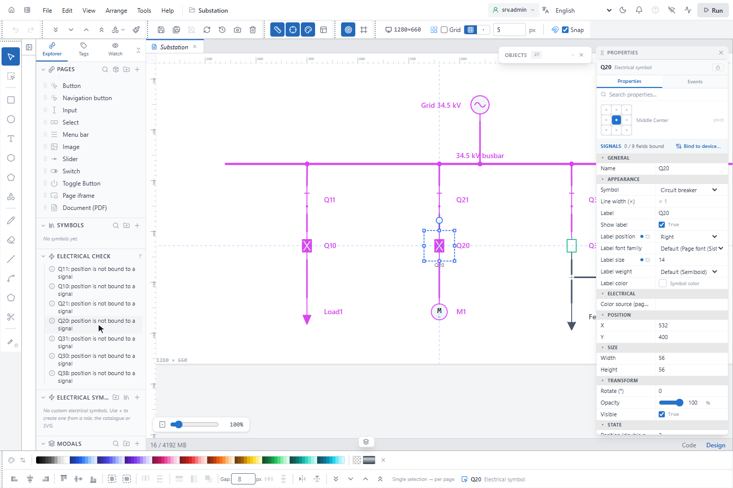
| Severity | Examples |
|---|---|
| Error | A source symbol whose source is not selected or not in the table; a user symbol whose definition is invalid or missing |
| Warning | A terminal or a wire end that is not connected; a wire end lying on another wire without being connected; a section not connected to any source; a link name without a partner |
| Information | A position not bound to a signal; an off-page connector without a name |
2. Start the simulation
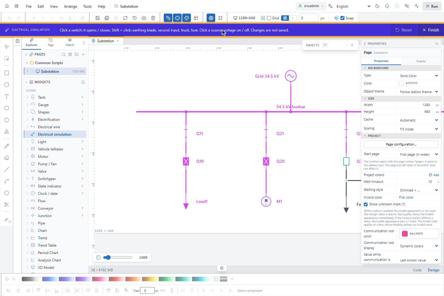
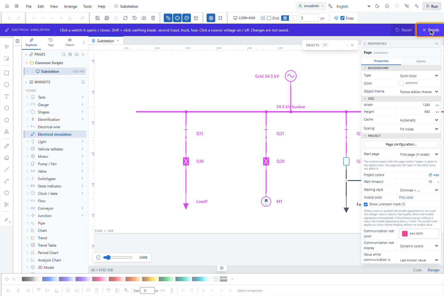
In WIDGETS, click Electrical simulation. A purple bar opens at the top of the editor with the instructions and the number of changed objects.
3. Operate switches
Click a switch to open or close it; the colors are calculated again at once.
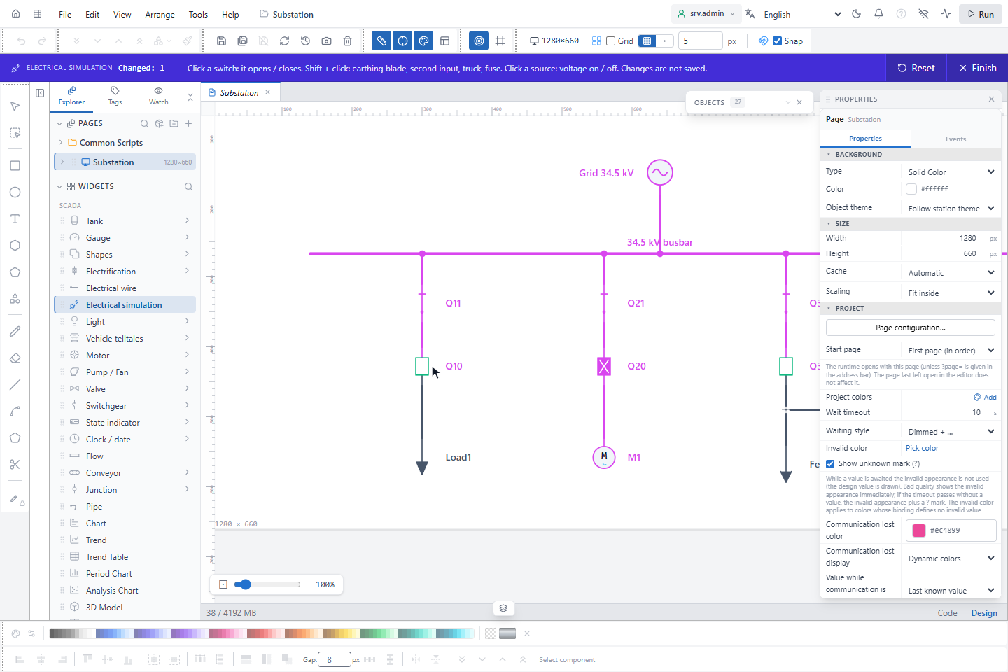
- On a tripped breaker, the first click resets the trip.
- Shift+click operates the earthing blade of a 3-position switch, the second input of an ATS, the truck of a draw-out breaker or a fuse.
- Clicking a source switches its voltage off and on.
4. Try an interlock
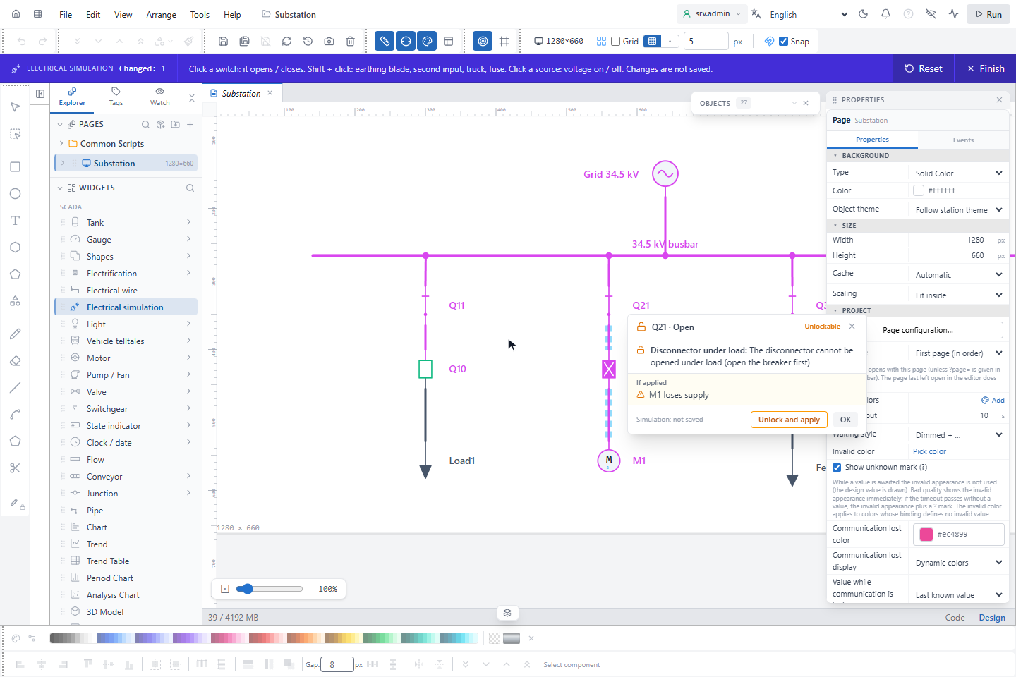
Interlocks are checked in the simulation as for a real command. A blocked operation opens a window with the rule, its level (Unlockable or Locked) and what would happen if it were applied; the affected sections are marked on the diagram. For an unlockable rule, Unlock and apply applies the operation in the simulation only; OK closes the window.
For the rules, see Topological interlocking.
5. Reset and finish
Reset returns all switches to their design position. Finish or Esc ends the simulation.
Simulated values are not saved and are not in the undo history; they are cleared when you finish or change the page.