Modbus TCP
The Modbus TCP driver reads and writes registers and coils of Modbus TCP devices: PLCs, meters, drives and Modbus gateways. For what all drivers have in common, see How drivers work.
Protocol and role
| Role | Client (master). YTCC connects to the devices; it does not accept Modbus connections. |
| Transport | Modbus TCP. |
| Default port | 502 |
| Devices per driver | Any number. Devices with the same host and port, for example several units behind one Modbus gateway, share one TCP connection. |
| Driver type | Modbus TCP (modbus_tcp) |
Device parameters
Set these on the device in Drivers → devices (see Add drivers and devices). An empty box uses the default shown in it.
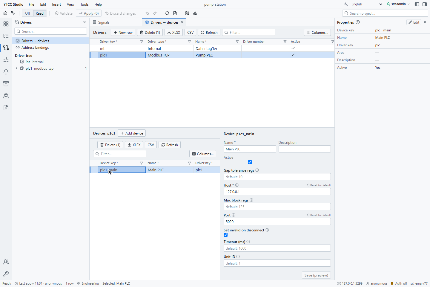
| Parameter | Default | Range | Meaning |
|---|---|---|---|
| Host | — (required) | IP address or host name | Address of the device or of the Modbus gateway. A host name is resolved through DNS. |
| Port | 502 | 1–65535 | TCP port of the device. |
| Unit ID | 1 | 0–255 | Modbus unit identifier (slave address). Devices usually use 1–247; behind a gateway it selects the device. |
| Timeout (ms) | 1000 | 1 and more | How long the driver waits for each answer, for reading and for writing. |
| Gap tolerance regs | 10 | 0–65535 | How many unused registers may lie between two signals before the driver reads them in separate requests. |
| Max block regs | 125 | 1–125 | Most registers in one read request (function codes 3 and 4). |
| Set invalid on disconnect | on | on / off | When the connection is lost, mark all signals of the device as Bad · Not connected. When off, the signals keep their last value and quality. |
Changing Host, Port, Unit ID, Timeout (ms) or Set invalid on disconnect reconnects that device. Changing Gap tolerance regs or Max block regs takes effect without dropping the connection.
When you import devices from a file, the host, port, unit ID and timeout come from the file.
Signal address
Set the address on the Value source tab of the signal, under Address — Modbus TCP.
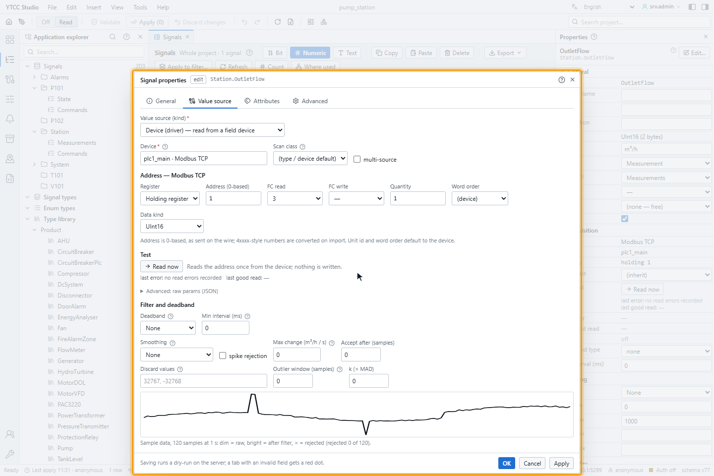
| Field | Values | Meaning |
|---|---|---|
| Register | Holding register, Input register, Coil, Discrete input | The register table. |
| Address (0-based) | 0–65535 | The address as it is sent to the device. Holding register 40001 is address 0. |
| FC read | 3, 4, 1, 2 | Function code for reading: 3 holding registers, 4 input registers, 1 coils, 2 discrete inputs. |
| FC write | empty | Leave it empty. The value is written to the address that is read; see Writing. |
| Quantity | 1 and more | Number of registers the value takes. |
| Word order | (device), Big endian, Little endian, Word swapped | Order of the registers of a 32- or 64-bit value. See below. |
| Data kind | (from signal type), Bit, Int16 … Float64, Text, Bit field | How the registers are read. See Data kinds. |
Read now reads the address once from the device and shows the value or the error; nothing is written. Use it to check an address while you set it up.
Address syntax in import files
When you import signals from a file (see Import and export with Excel or CSV), write the address in the address column in one of these forms:
| Form | Example | Result |
|---|---|---|
| Register word and 0-based address | holding 1, input 0, coil 0, discrete 5 | Holding register 1, input register 0, coil 0, discrete input 5 |
| Short words | hr, ir, co, di, or 4x, 3x, 0x, 1x | Same as the words above |
| 1-based Modbus number, 5 or 6 digits | 40001, 400001, 30010, 00001, 10001 | First digit: 4 holding, 3 input, 0 coil, 1 discrete; the rest minus 1 is the address |
A bare number such as 200 is rejected. The import sets the read function code and the quantity from the register
and the data type (2 registers for 32-bit types, 4 for 64-bit types).
Word order
| Word order | Byte order of a 32-bit value A B C D |
|---|---|
| Big endian (default) | A B C D, the Modbus standard |
| Word swapped | C D A B |
| Little endian | D C B A |
(device) uses big endian. The fourth order, byte swapped (B A D C), is set in Advanced: raw params (JSON)
("word_order": "BADC").
Data kinds
| Data kind | Registers | Value |
|---|---|---|
| Bit | 1 coil or discrete input | On or off |
| Int16, UInt16 | 1 | Signed or unsigned 16-bit integer |
| Int32, UInt32, Float32 | 2 | 32-bit integer or floating-point number |
| Int64, UInt64, Float64 | 4 | 64-bit integer or floating-point number |
| Text | Quantity | Text, two characters per register |
| Bit field | 1 | Several bits of a register, as a number. Set the first bit and the number of bits in Advanced: raw params (JSON) (bit_offset, bit_count). |
(from signal type) uses the data type of the signal. A scale and offset set on the signal are applied after reading (value = raw × scale + offset); the raw register value stays available as the raw value of the signal.
Under Filter and deadband you can suppress small changes (Deadband), set a Min interval (ms) between two values, smooth the value and reject spikes. These settings apply to every driver.
Reading
The driver polls. It groups the signals of a device by function code and scan period, and reads neighbouring registers in one request: up to Max block regs registers (120 when a 32- or 64-bit value is in the block) and up to 2000 coils or discrete inputs, as long as no gap is larger than Gap tolerance regs. When the connection opens, it reads every block once; the device counts as connected after the first good answer.
The scan class of the signal sets how often each block is read; see How often values are read.
Writing
A signal can be written when its Access is Read / Write or Write only. The driver chooses the function code from the value:
| Value | Function code |
|---|---|
| Coil (Bit) | 5 Write single coil |
| 16-bit register | 6 Write single register |
| 32- and 64-bit values, text | 16 Write multiple registers |
- The value is written to the address that is read, so give a writable signal a Register, an Address and an FC read.
- A signal with data kind Bit is written as a coil (function code 5). Make it writable only when its Register is Coil.
- Bit, Int16 … Float64 and Text values can be written.
- If the device is not connected, the command is rejected at once. A command waiting for a device that goes offline is cancelled, not sent later.
- Each device accepts up to 4 waiting commands; more are rejected as Previous command in progress.
- If the device answers with an exception, the command is rejected with Device returned an error; the connection stays up.
- If the signal is set to read back after writing, the driver reads the value again right after a successful write.
For how operators send and confirm commands, see Send commands.
Quality mapping
| Situation | Quality of the signals |
|---|---|
| Read succeeded | Good |
| The answer is too short or cannot be converted | Bad for that signal |
| Exception 02 (illegal data address) | The driver splits the request until it finds the rejected address; that signal is Bad, the others are read normally |
| Other exceptions (01, 03, 04 …) | Bad for the signals of that request; the connection stays up |
| Timeout, connection error, exception 05 or 06 | The connection is closed and opened again; with Set invalid on disconnect, all signals of the device are Bad · Not connected |
Read the value together with its quality. Do not use a value whose quality is Bad or Bad · Not connected; see Read values and states.
Time stamps
Modbus does not carry the time of a value. The time a value arrives in YTCC is used for both time stamps, and the signal details show Time source: protocol carries no time.
Diagnostics
- Device status. The device is shown as connected after the first good answer and as not connected when the connection is lost. A device with an invalid setting does not connect and shows the reason.
- Communication alarm. One alarm per device after 5 seconds without connection; see How drivers work.
- Read now. On the Value source tab, Read now shows the last read error of the signal, for example Modbus exception 02 — Illegal data address (holding 102, unit 3, FC3) or Timeout — no response from 10.0.0.30:502 (unit 1) within 1000 ms.
- Signal details. On the runtime screen, the signal details show the driver, the device and the protocol address, for example holding 1. See Look at the details of a signal.
| Symptom | Likely cause |
|---|---|
| All signals of the device Bad · Not connected | Wrong host or port, device off, firewall, or the unit does not answer within Timeout (ms) |
| One signal Bad, the others good | Address outside the device's register map (exception 02), or wrong quantity |
| 32-bit value looks wrong but changes | Wrong Word order |
| Value off by a register | The device documentation counts from 1: use address minus 1 |
| Command rejected with Signal not found | The signal is not writable; set Access to rw on the signal |
Supported function codes
| Code | Function | Supported |
|---|---|---|
| 1 | Read coils | Yes |
| 2 | Read discrete inputs | Yes |
| 3 | Read holding registers | Yes |
| 4 | Read input registers | Yes |
| 5 | Write single coil | Yes |
| 6 | Write single register | Yes |
| 15 | Write multiple coils | Yes, not used for single values |
| 16 | Write multiple registers | Yes |
The driver recognises exception codes 01–08, 10 and 11 and shows their names in the error text.