Bind signals to electrical symbols
A single-line diagram becomes live when its switches show the real positions from the field. Each electrical symbol has STATE fields for its position and protection signals, a Command signal for operation from the run screen and, where it fits, MEASUREMENT fields for a voltage measurement.
Before you begin
- The diagram is drawn: see Place symbols and draw wires.
- The signals exist in the project, for example from a driver: see Create signals.
Steps
1. Bind the position and protection signals
Select a switch. In PROPERTIES under STATE, bind each field to a signal as for any other object (see Bind objects to signals). The fields shown depend on the symbol:
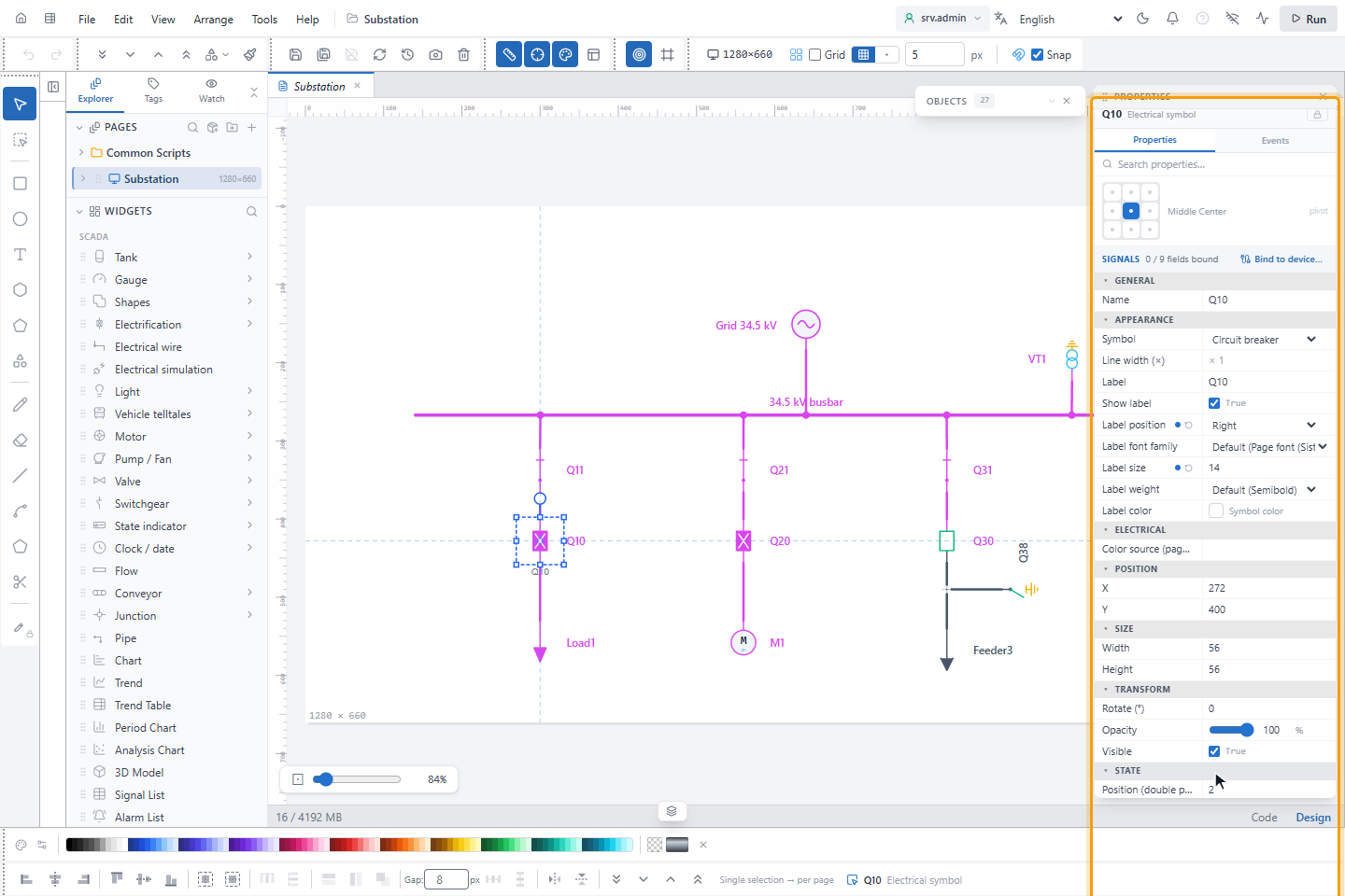
| Field | Value |
|---|---|
| Position (double point) | 0 intermediate, 1 open, 2 closed, 3 invalid, as IEC 60870-5 double points and IEC 61850 Dbpos. An on/off signal: on is closed. |
| Second position (double point) | Earthing blade of a 3-position switch, second input of an ATS |
| Trip (protection operated) | On: the protection has tripped the breaker |
| In test / withdrawn position | Draw-out breaker |
| Fuse blown | Fuse symbols |
| Earth fault (51N / 67N), Short circuit (50 / 51 / 21) | The breaker's relay has seen fault current; see step 4 |
| Voltage present | Source symbols: the source has voltage. It switches the source on and off; it is not a measurement. |
| Local control (L) | On: the switch is in local control, an L is shown and no remote command is sent |
Under CONTROL, set the Command signal that the run screen writes: on to close, off to open.
A value with bad quality, a value still awaited and a value that never arrived count as unknown: the switch shows a grey ? and the sections behind it are possibly energized. Manual (M) and simulated values are used like normal values. A value without communication keeps its last value; see Communication lost.
2. Bind a whole bay at once
When the signals of a device are grouped as an instance, for example TM1.Q10.Pos, TM1.Q10.Trip, click Bind to
device… in the SIGNALS line at the top of PROPERTIES. Enter the Instance path and choose, for each state
field, the element of the instance; Bind binds them all.
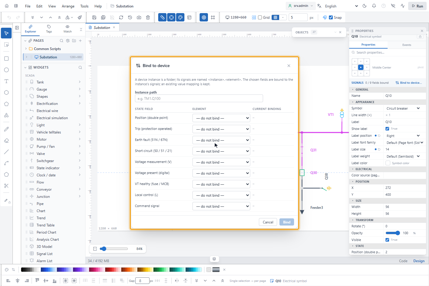
With several symbols selected, write {ad} in the path for the name of each symbol: TM1.{ad} binds Q10 to TM1.Q10.*
and Q20 to TM1.Q20.*. When an on/off signal is bound to a position, the mapping on → closed, off → open is set
automatically. An existing value mapping is kept.
3. Connect a voltage measurement
Voltage measurements can be bound on VTs, busbars, catenaries and third rails, outgoing feeders, overhead lines, cables and switches. A power meter or relay symbol has no terminal: bind its voltage to the busbar or VT it measures.
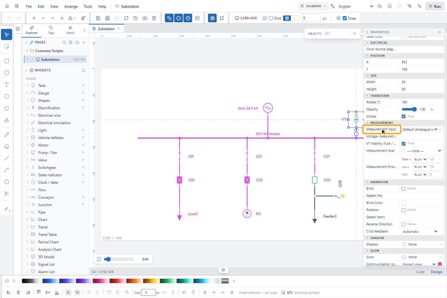
| Field | Meaning |
|---|---|
| Measurement input | Analogue voltage (V), Digital voltage present / absent or Analogue + digital |
| Voltage measurement (V) | Analogue measurement in volts, judged with the thresholds of the level |
| Voltage present (digital) | 1 voltage present, 0 no voltage (from a VT or a voltage presence relay); no thresholds |
| VT healthy (fuse / MCB) | Optional. If bound and off, or with bad quality, the measurement proves nothing. |
| Measurement level | The voltage level whose Un and thresholds apply |
| Measured terminal | On a two-terminal symbol: Top (t) (default) or Bottom (b) |
| Measurement thresholds | Override the level's thresholds for this point only; an empty box keeps the level's value |
Bind VT healthy wherever you can. A tripped VT fuse makes the measurement say "no voltage" while the line may be live; field practice before earthing checks three things together: disconnector open, no voltage, VT MCB healthy. YTCC uses a measurement as proof only while the VT is healthy.
With both analogue and digital bound, the analogue value wins; if they disagree, it is a measurement mismatch. Bad quality, communication lost, a VT fault, or % thresholds without Un mean the measurement proves nothing.
4. Bind the fault signals
On breakers and feeders with trip information, bind Earth fault (51N / 67N) and Short circuit (50 / 51 / 21) to the trip or start signal of the relay.
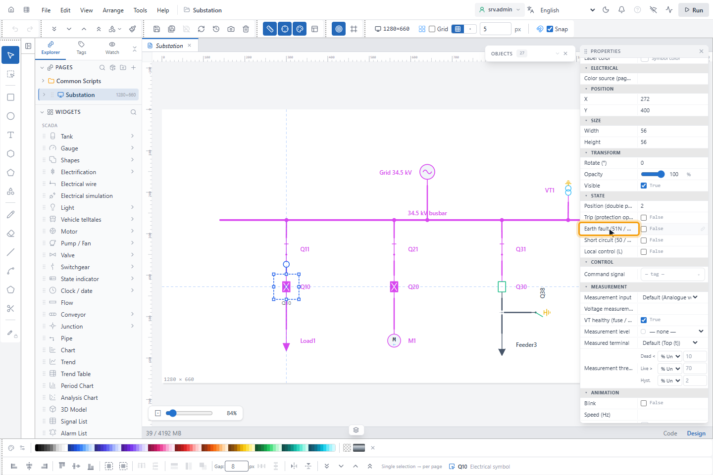
YTCC then shows the fault zone: the section below the last breaker that saw the fault current, through cables, lines and reactors, up to the next switch, fuse or transformer. A short circuit is red and an earth fault amber, both blinking, in front of all other states.
- When only one end of the breaker is energized (it has tripped), that end is the supply side. Otherwise the top terminal (t) is taken as the supply side: place breakers with the supply above.
- Protection signals with bad quality or without communication do not create a zone.
- The topology service raises an alarm for each faulted section: by default short circuit with priority critical, earth fault high. The alarm clears when the protection signal goes off.
5. Set the consumer criticality
Unsupplied consumers are reported with one alarm per outage area: when a feeder breaker opens, all consumers behind it are in one alarm. Select a load symbol (load, motor, outgoing feeder…) and set Consumer criticality under ELECTRICAL:
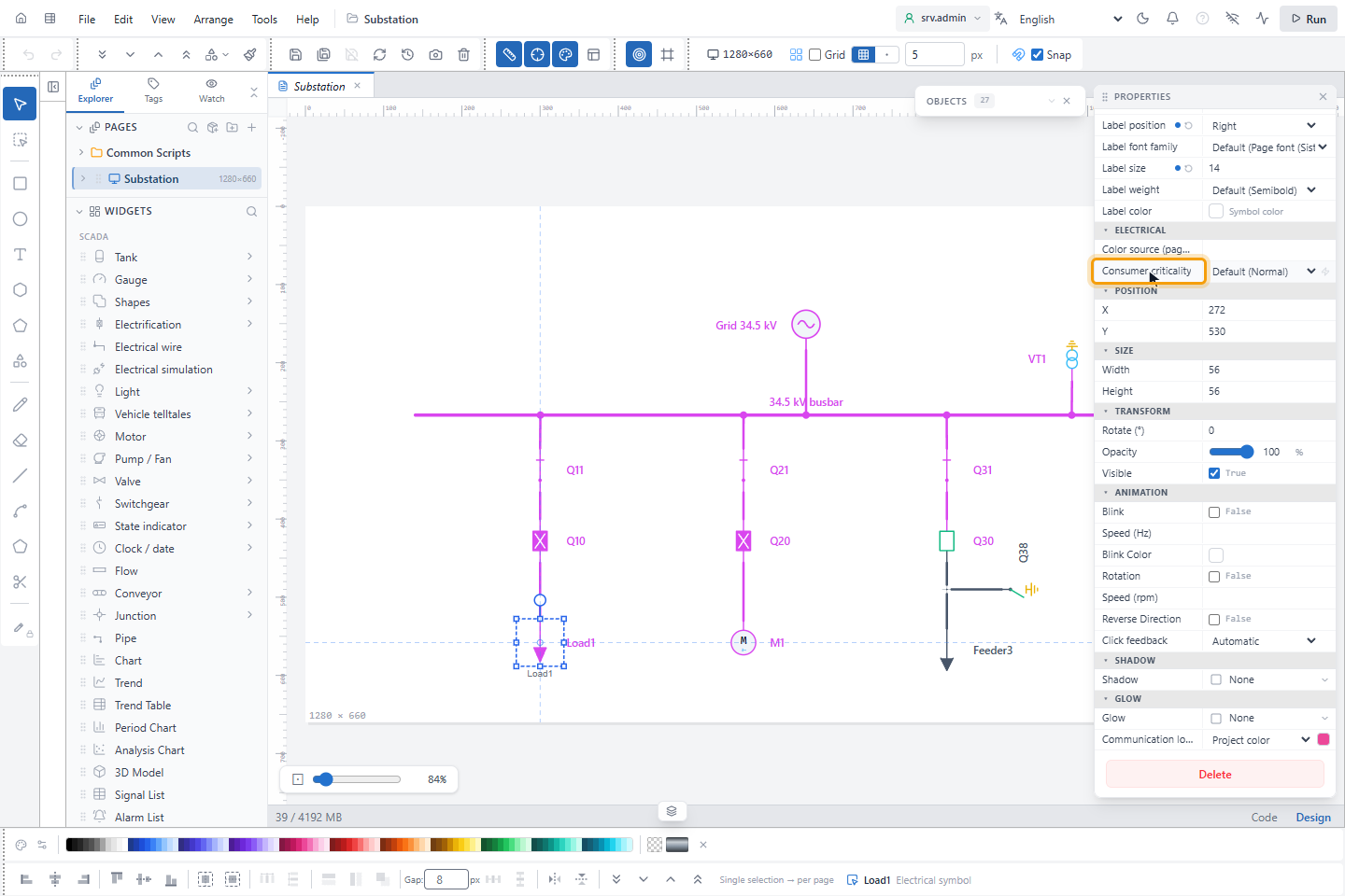
| Criticality | Example | Alarm priority |
|---|---|---|
| Normal (default) | General load | Low |
| Important | Pumping station, process load | High |
| Critical | Signalling supply, hospital | Critical |
The area alarm takes the priority of its most critical consumer and names the critical and important consumers first. If the outage grows and takes in a more critical consumer, the alarm is raised again at the higher priority, and an acknowledgement is cleared. These priorities are the defaults; Topological alarms in the project settings can set another priority per alarm type or switch a type off, see Set the interlock rules.
Result
Run the project: the switches show the field positions and the diagram is colored by them. Missing bindings are listed under ELECTRICAL CHECK in the Explorer.