Import a single-line diagram from IEC 61850 SCL
An IEC 61850 substation configuration file (SSD or SCD) describes the single-line structure of a substation: voltage levels, bays, the equipment in them and how their terminals are connected. YTCC can draw the diagram from it on the open page, choose the sources and bind the switches to the IEC 61850 signals of the project.
Before you begin
- The page that should receive the diagram is open in the screen editor; an empty page is easiest.
- The project's Electrification module is on: click an empty place on the canvas and, in PROPERTIES under PROJECT, tick Modules › Electrification. A new project has it off. After changing it, save and restart the project; see Place symbols and draw wires.
- To bind signals, the IEC 61850 signals of the IEDs are already in the project (see IEC 61850). Without them the diagram is drawn, but the switches stay unbound.
Steps
1. Open the import
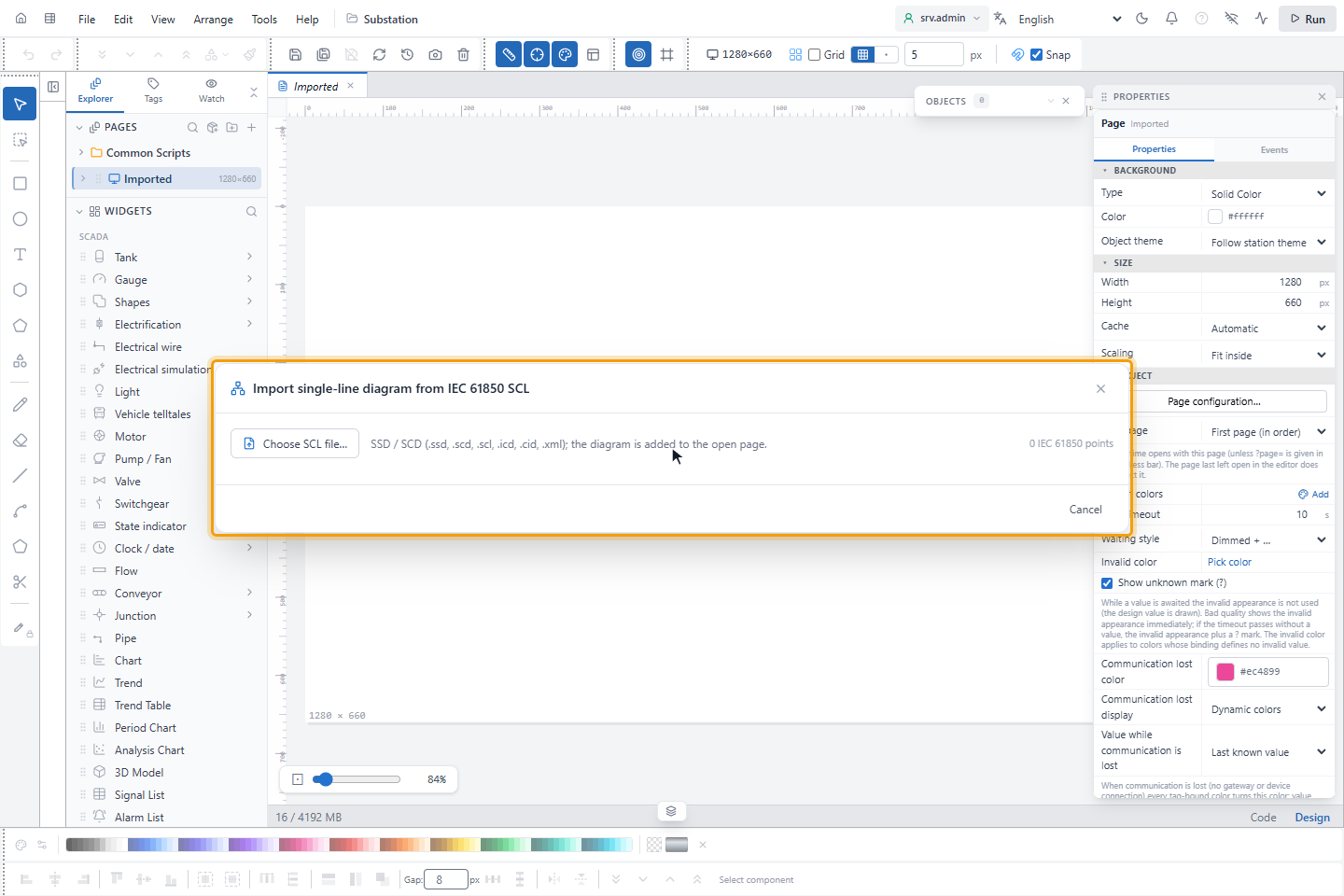
In WIDGETS, click Electrification and, at the bottom of the symbol list, Import single-line diagram from IEC
61850 SCL…. Click Choose SCL file… and select the file: .ssd, .scd, .scl, .icd, .cid or .xml, at most
64 MB.
2. Check the preview and the report
The dialog shows a preview of the diagram and a summary: the numbers of substations, voltage levels, bays, devices and connections, the layout, how many objects are new, will be updated or removed, the result of the electrical check of the new diagram and how many signals were bound.
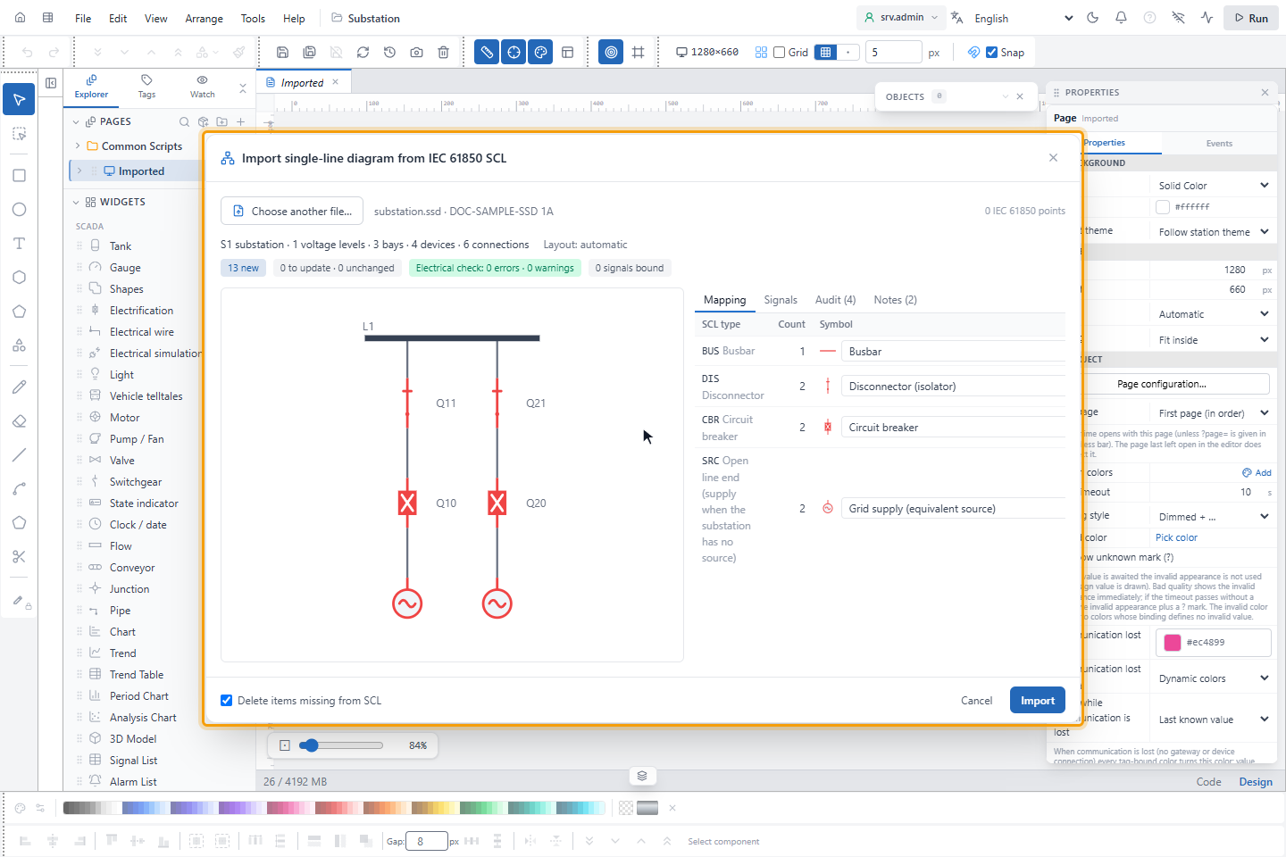
The tabs list the details:
| Tab | Shows |
|---|---|
| Mapping | Each SCL device type with its number and the symbol it becomes |
| Signals | The positions, local control and trip signals found for each switch |
| Audit | References without a signal, switches without logical nodes, interlocking (CILO) information |
| Notes | Decisions taken by the import, for example where a grid supply was assumed |
How the diagram is built:
- Layout. If every device in the file has diagram coordinates, they are used. Otherwise YTCC lays it out: voltage levels from top to bottom, busbars horizontal, bays as vertical columns; a bay that feeds a higher level, such as the low-voltage side of a transformer, is placed above its busbar.
- Busbars. A connectivity node in a bay without two-terminal equipment, for example a bay
BB1that only holds a node, becomes a busbar. - Line ends. An open line end becomes an outgoing feeder. If the substation has no source, the open ends of the highest voltage are taken as grid supplies; a note says so, and you can change the symbol in Mapping.
- Sources. Each voltage level uses the source of the level with the same nominal voltage. If there is none, a new level and source are added, for example 11 kV; the report shows them.
- Signals. The logical node references of each device are matched with the IEC 61850 signals of the project: the
position from XCBR or XSWI
Pos.stVal(otherwise CSWI), local control fromLoc.stValand trip from PTRCTr.general.
3. Adjust the mapping
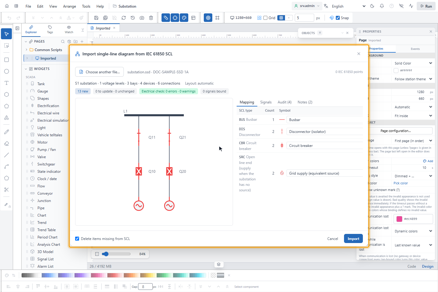
On Mapping, choose another symbol for an SCL type if needed, for example a draw-out breaker for CBR. The mapping is saved in the project when you import, and used for the next import.
| SCL type | Symbol |
|---|---|
| CBR | Circuit breaker |
| DIS | Disconnector (isolator); with one terminal earthed: Earthing switch |
| VTR, CTR | Voltage transformer, Current transformer |
| PTR | Power transformer (2 windings) or Three-winding transformer |
| GEN, SMC | Synchronous generator |
| IFL | Grid supply |
| BAT | Battery bank / BESS |
| CAP, PSH | Capacitor bank |
| REA | Line / shunt reactor |
| RES | Neutral grounding resistor |
| EFN | Petersen coil |
| CAB, GIL, LIN | Underground cable |
| BSH | Cable termination |
| MOT, FAN, PMP | MV induction motor |
| CON, SCR, TCF | Inverter, Rectifier, Variable frequency drive |
| TCR, RRC | STATCOM / SVC |
| SAR | Surge arrester |
A type without a mapping becomes a load (one terminal) or a cable (two terminals), and Mapping shows it as unmapped.
4. Import
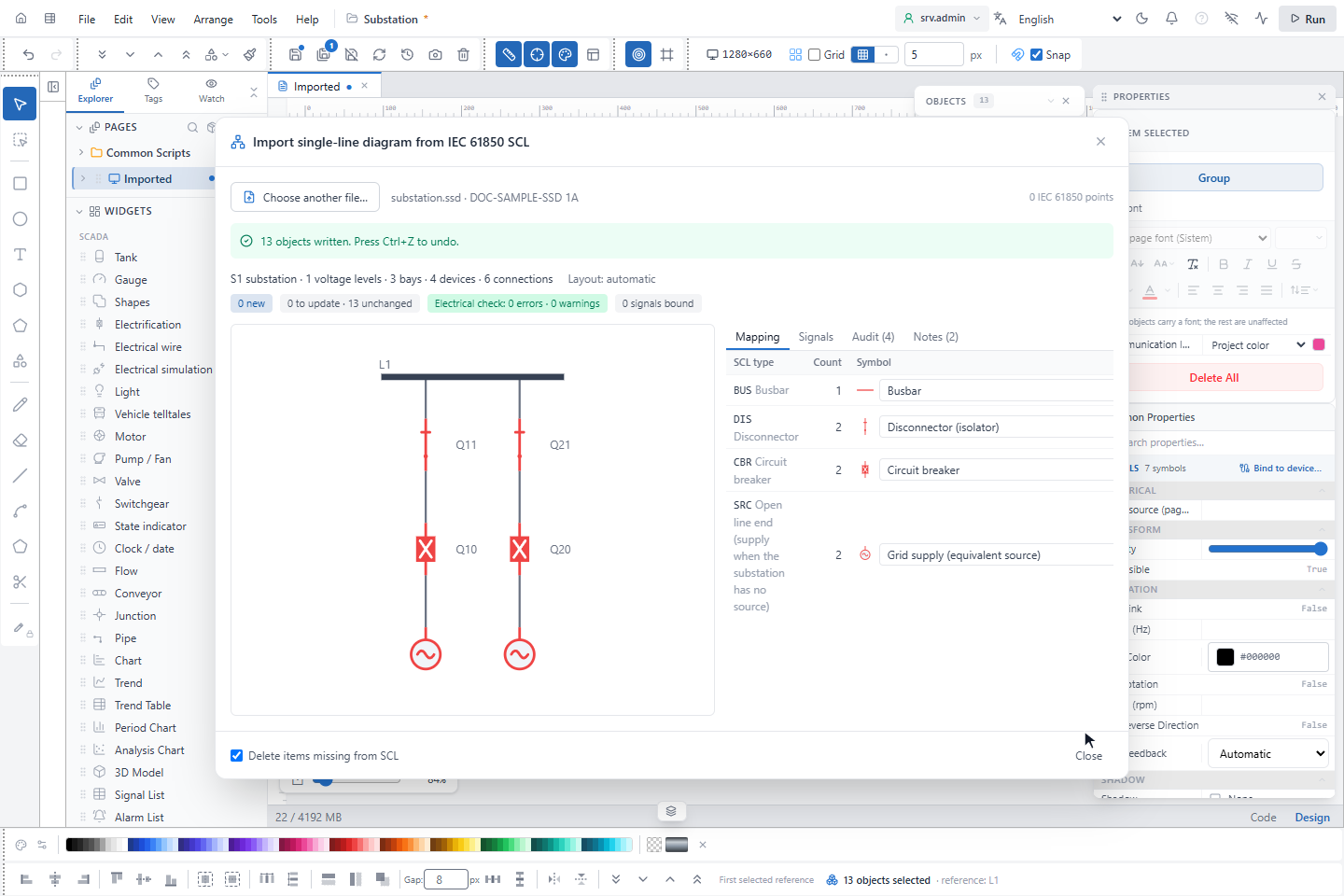
Click Import. If the electrical check has errors, the button reads Import anyway. The objects are written to the page in one step: Ctrl+Z removes them all again.
Import again
When the SCL file changes, import it again on the same page. Objects are matched by their path in the SCL file:
- symbols you moved, resized or rotated stay where they are;
- fields that the import writes (symbol, label, signal bindings, sources) and that you changed by hand keep your value; the others follow the file;
- a wire whose connections did not change keeps its route;
- with Delete items missing from SCL (on by default), the symbols and wires of devices that are no longer in the file are deleted.