User-defined electrical symbols
When the catalogue does not have the symbol you need, or your organisation draws to its own standard (IEC 60617, IEEE / ANSI 315, a company style), you can define your own electrical symbol. A user symbol takes full part in automatic coloring, interlocking, control and the server interlock, exactly like a catalogue symbol.
The principle: you bring the drawing, the role brings the meaning. How the symbol behaves in the network, its terminal slots, the states that must be drawn and the state colors are fixed by its role; you only decide how they look. A drawing mistake therefore cannot break the network calculation or an interlock.
Before you begin
- The project is open in the screen editor.
Steps
1. Start a new symbol
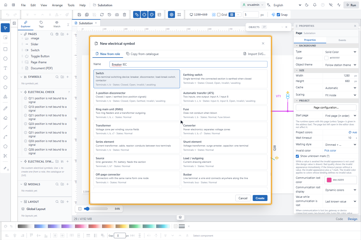
In the Explorer, click + (New electrical symbol…) in the ELECTRICAL SYMBOLS section. Type a name and choose how to start:
- New from role: choose the role; terminal slots and required states come with a starter drawing.
- Copy from catalogue: all state drawings, terminals and capabilities of a catalogue symbol are copied (Copy and edit). The role of the copy cannot be changed.
- Import SVG…: see SVG files.
New folder groups the symbols in the Explorer.
2. Get to know the editor
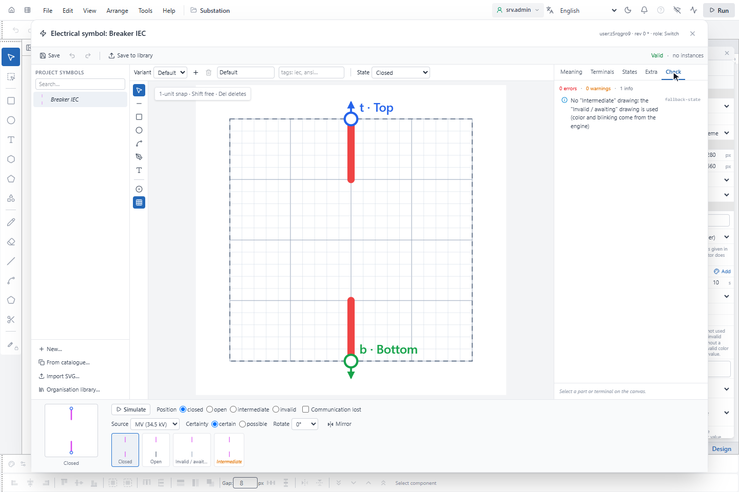
Click Create. The editor shows the symbol list on the left, the drawing canvas in the middle (a box of 100 × 100 units with 1-unit snap; Shift places freely, Del deletes), the tabs Meaning, Terminals, States, Extra and Check on the right, and the preview strip at the bottom with every state as a thumbnail.
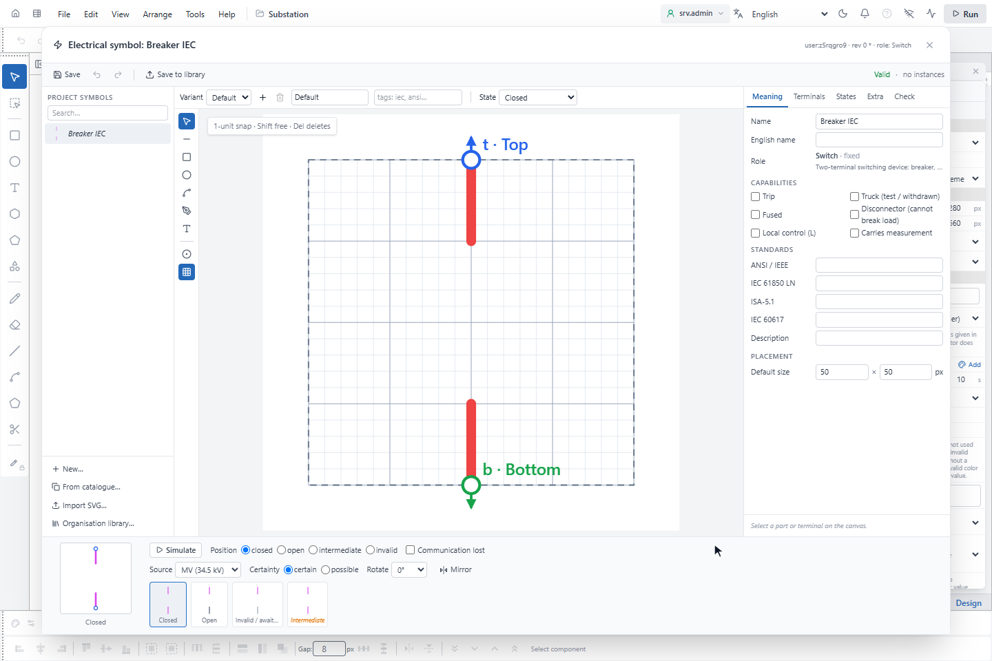
On Meaning you set the name, the English name, the capabilities the role allows (for a switch: Trip, Truck (test / withdrawn), Fused, Disconnector (cannot break load), Local control (L), Carries measurement), the standard designations and the default size.
3. Place the terminals
On Terminals, every terminal belongs to a slot (t, b or c); the network only sees the slot.
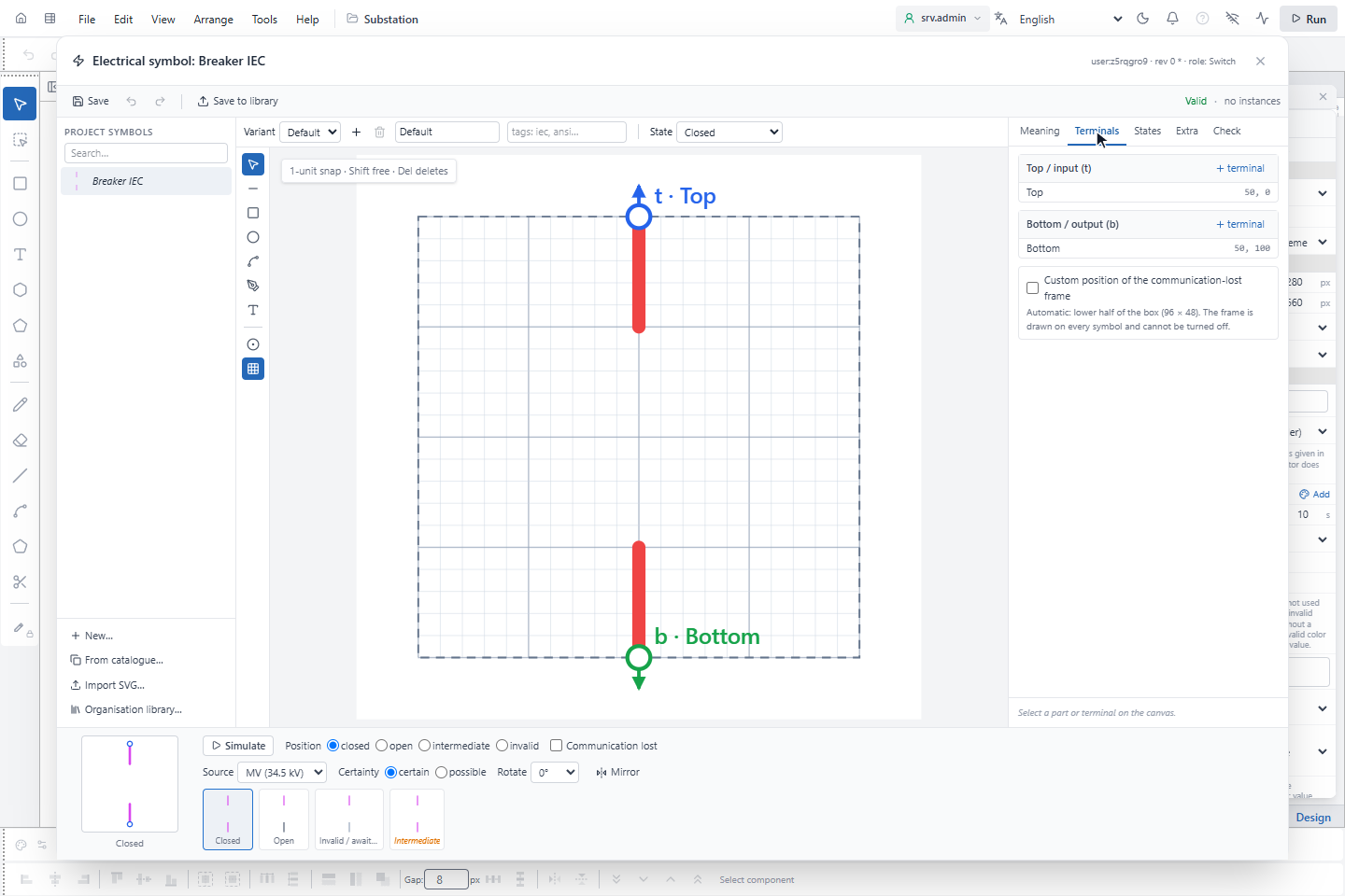
- A terminal can be anywhere inside the box or on its edge, in one of eight directions, and can have a visible name such
as
X1. - Several terminal points can share a slot; they are one electrical node.
- On a busbar role the terminal is a line, set by dragging its ends.
- Terminals of different slots must be at least 6 units apart, otherwise a wire would snap to the wrong one.
- When a terminal moves, connected wire ends follow. Adding or removing a slot asks for confirmation and reports how many instances and wire ends are affected.
4. Draw the states
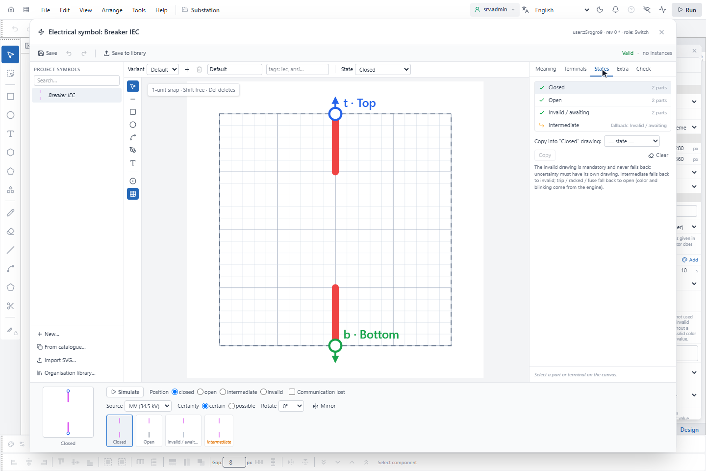
On States, every state has its own drawing. Copy into copies one drawing to another as a starting point.
| State | Required | If not drawn |
|---|---|---|
| Closed, Open | On switching roles | — |
| Invalid / awaiting | Always on roles with a position | No fallback: uncertainty must have its own drawing |
| Intermediate | No | The invalid drawing, with the intermediate color and blinking |
| Trip, Truck, Fuse blown | No | The open drawing, with the trip color and blinking, or the truck mark |
| Earthed, Input A, Input B | On 3-position and transfer roles | — |
| Voltage present / no voltage / residual / no evidence | On measuring roles | The measurement badge of YTCC |
Communication lost and possible (dashed) are not drawn: YTCC adds them. The communication lost frame appears on every symbol and cannot be switched off; on Terminals you can choose where it goes, otherwise it covers the lower half of the box.
Every drawn part carries a color role or a fixed color. You do not pick state colors; you say which role's color a part carries:
| Group | Roles | Carries |
|---|---|---|
| State roles | Wt Wb Wc (terminal lines), L, G, O, X, B Bw Bg (body), Fb Fc Ft, Cw Ct Cb Cc, RpL RpT, W7 W5, Tl | Network or state color; pattern and blinking come from YTCC |
| Neutral roles | A, D, Af, Rp, T, Tw | Accent, text, fixed detail |
| Fixed | no role | Its own color; does not change with the state |
Each state drawing needs at least one part with a state role, or the state is invisible. A part with a state role cannot be dashed or transparent: dashes and visibility are state information (earthed, possible, second source).
5. Check the symbol
Check lists the problems; click a row to select the tab, terminal, part or overlay concerned. The same rules are applied when the project is saved on the server.
| Code | Level | Meaning |
|---|---|---|
missing-state | Error | A required state, or a state of a capability that is on, is not drawn |
slot-count | Error | A slot is missing or not allowed for the role; a busbar without a line terminal; the measured terminal points to a missing slot |
terminal-outside | Error | A terminal is outside the box |
terminal-overlap | Error | Terminals of different slots are closer than 6 units |
no-state-part | Error | A state drawing has no part with a state role |
overlay-reserved-paint | Error | An overlay part uses a state color or state role |
state-dash | Error | A part with a state role is dashed or transparent |
variant-slots | Error | Variants have different slots |
unknown-field | Error | An overlay condition or text reads an undefined field or parameter |
bad-definition | Error | The definition is broken, typically in a file edited by hand |
overlay-covers-state | Warning | An opaque overlay covers more than 15 % of the state parts |
terminal-unattached | Warning | A terminal does not touch the end of a terminal line (Wt / Wb / Wc) |
fallback-state | Information | An optional state is not drawn; its fallback is used |
6. Simulate
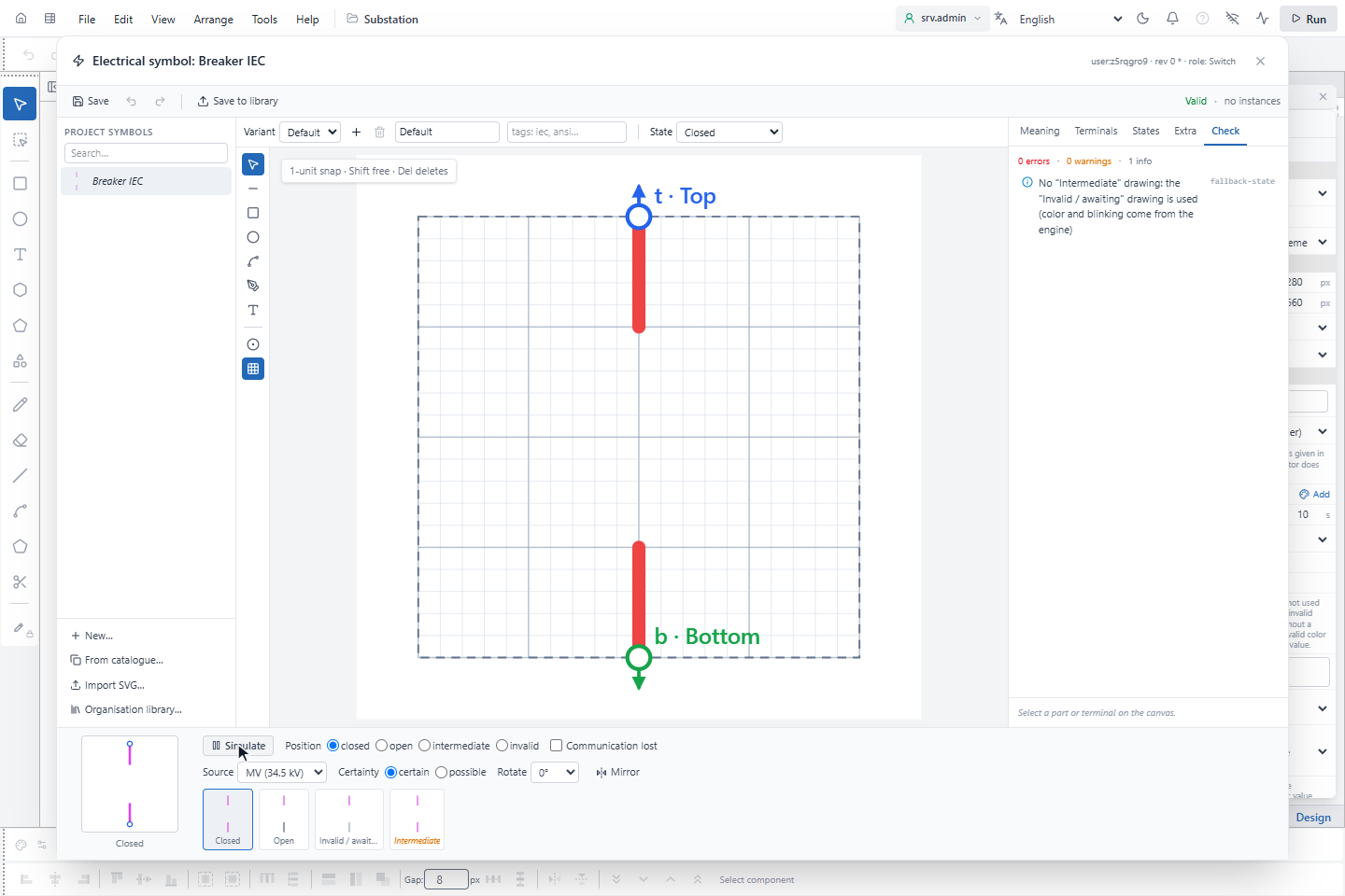
Simulate in the preview strip draws the symbol with the real YTCC output: position, trip, truck, fuse, local, the level color of a chosen source, possible (dashed), communication lost, measurement, rotation and mirroring.
7. Save
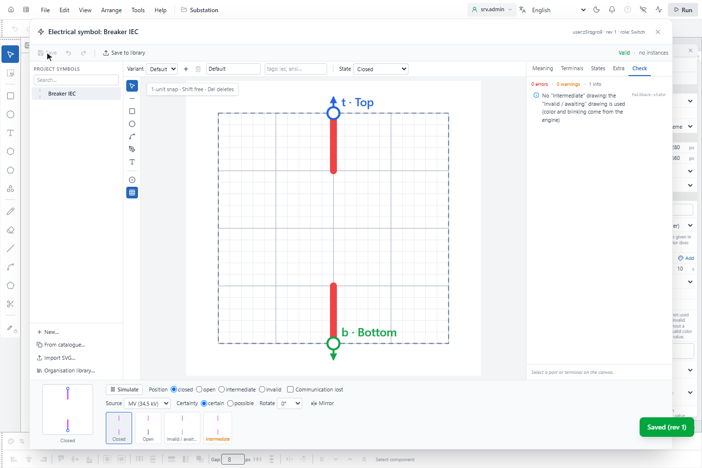
Click Save. Each save increases the revision.
- A symbol with errors is saved as a draft and cannot be placed on a page; it is grey in the symbol list.
- If the symbol already has instances, a version with errors is not saved and the last valid version stays in effect. Saving a version with changed slots or a changed role first shows how many instances and wire ends are affected (Save anyway).
- A symbol with instances cannot be deleted: choose Replace with… a symbol of the same role and Replace and delete; terminals are matched by slot.
- A project whose pages use a missing or invalid symbol is not saved.
On the run screen, a symbol whose definition is missing or invalid is drawn as a red ?. It counts as undefined in the network, its control and the earthing around it are locked, and ELECTRICAL CHECK shows an error. It never falls back to another catalogue symbol with a different role.
Roles
The role is the behavior of the symbol in the network.
| Role | Terminal slots | Required states | Capabilities |
|---|---|---|---|
| Switch | t, b | Closed, open, invalid | Trip, truck, fused, disconnector (cannot break load), local control, measurement |
| Earthing switch | t | Closed, open, invalid | Local control |
| 3-position disconnector | t, b | Closed, open, earthed, invalid | Disconnector (on by default), local control |
| Automatic transfer (ATS) | t, c, b | Input A, input B, open, invalid | Local control |
| Ring main unit (RMU) | t, b, c | Normal | — |
| Fuse | t, b | Normal, blown | — |
| Transformer, Converter | t, b, (c) | Normal | One or two source fields |
| Series element | t, b | Normal | Load, measurement |
| Shunt element | t | Normal | Load |
| Source | t, (b) | Normal | Voltage present signal, measurement |
| Load / outgoing | t | Normal | Measurement |
| Off-page connector | t | Normal | — |
| Busbar | Line | Normal | Measurement |
| Voltage measuring point | t | Voltage present, no voltage, residual, no evidence | Measurement always on |
| Voltage measuring point (line) | Line | Voltage present, no voltage, residual, no evidence | Measurement always on |
Slots in brackets are optional.
Variants
A symbol can have several drawing sets, for example a compact IEC and a detailed ANSI drawing, with the same meaning.
All variants have the same slots; terminal positions may differ. Give each variant tags such as iec, ansi, compact
or detailed. The variant used is the first match of: the Variant field of the object, the drawing style of the
page, the drawing style of the project, the first variant. Changing the variant does not change the network; wires stay.
Overlays and parameters
On Extra you add overlays: indicators that do not take part in the network, such as cable connected, test position, spring charged or SF6 low.
- An overlay is bound to an extra field (on/off, number or text, for example
cableIn) or to a symbol parameter, with an optional condition: equal, not equal, greater, less, is true, is false. - Overlay texts may contain
{label},{name},{x.<field>}and{p.<parameter>}; these only insert values and run no expression. - A symbol parameter, for example the rated current or the cell number, is a fixed value per instance.
- Bind to device… also binds the extra fields.
- An overlay never changes the network, the coloring or an interlock, and it cannot cover the state: overlays are drawn between the fixed parts and the state parts.
Measurement
A user symbol carries a voltage measurement in one of two ways: as a Voltage measuring point role (one terminal or a line on a busbar), whose four measurement drawings are required; or with the Carries measurement capability on a switch, busbar, series element, load or source, whose measurement drawings are optional. The measurement inputs are bound on each instance, see Bind signals to electrical symbols.
Organisation library
Every user symbol used or edited in a project is stored completely in the project: backups, exports and packages contain all of them. The organisation library on the server is only a source of copies.
- Save to library in the editor writes the complete definition to the library. It is available only for a saved version without errors, and only to server administrators.
- Organisation library… opens the library: copy a symbol into the project, or, when the library has a newer version (newer version in library (rev 3 → 5)), Show difference / update and Copy update into project. If the project copy has local changes, Detach as local copy and update keeps them apart.
- Nothing is synchronised automatically. The identifier of a symbol is fixed; renaming it does not break pages.
SVG files
Import SVG… reads a symbol drawing in the browser. The file may have at most 512 KB and 2000 elements; a larger or
unreadable file is refused. Allowed elements are g line rect circle ellipse path polyline polygon text; scripts,
foreign objects, images, use, styles, links, media, animations and paint with url(…) are removed. The drawing is
scaled to 100 units on its long side and centred. Information that is missing is listed on Check and set in the
editor.
| What | How to write it in the SVG |
|---|---|
| Terminal | data-ytcc-terminal="t" (or id="term:t"), slots t, b, c; optional data-ytcc-name="Feeder". The centre of the element is the terminal point; the element itself is removed. |
| Busbar line terminal | A line with data-ytcc-terminal="bus" |
| State | Groups <g data-ytcc-state="open"> under the root: closed, open, intermediate, invalid, tripped, racked, blown, earthed, inputA, inputB, normal; for measurement live, dead, residual, noEvidence. Without groups the whole drawing is normal / closed. |
| Color role | data-ytcc-role="L" or class="ytcc-L"; without a role the part keeps its color |
| Overlay | <g data-ytcc-overlay="cableIn"> |
| Role | data-ytcc-kind="switch" on the root or the symbol group; otherwise the import asks |
| Several symbols | Several <g data-ytcc-symbol="…"> in one file |
<svg viewBox="0 0 100 100" xmlns="http://www.w3.org/2000/svg">
  <g data-ytcc-symbol="Breaker IEC" data-ytcc-kind="switch">
    <circle data-ytcc-terminal="t" data-ytcc-name="Busbar side" cx="50" cy="2" r="1"/>
    <circle data-ytcc-terminal="b" data-ytcc-name="Feeder" cx="50" cy="98" r="1"/>
    <g data-ytcc-state="closed">
      <line class="ytcc-Wt" x1="50" y1="2" x2="50" y2="30"/>
      <rect data-ytcc-role="B" x="34" y="30" width="32" height="40"/>
      <line class="ytcc-Wb" x1="50" y1="70" x2="50" y2="98"/>
    </g>
    <g data-ytcc-state="open"> … </g>
    <g data-ytcc-state="invalid"> … </g>
    <g data-ytcc-overlay="cableIn"> … </g>
  </g>
</svg>