Diagrams across several pages
A large network does not fit on one page. YTCC calculates the colors and the interlocks for the whole project, not per page: a page without a source of its own is colored from the source on the page that feeds it, and the live positions of switches on pages that are not open are taken into account.
Before you begin
- The first page of the diagram is drawn. See Place symbols and draw wires.
Steps
1. Place an off-page connector
Where the network continues on another page, place the Off-page / voltage label (LV-MV) symbol from Lines,
busbars & cables and connect the wire to it. Under ELECTRICAL, type a Link name, for example F3.
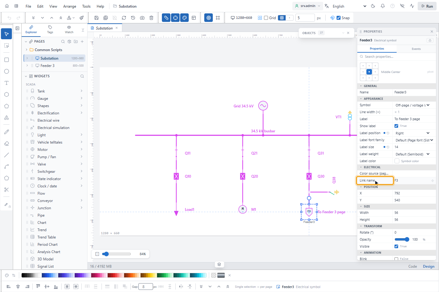
Connectors with the same link name are one electrical point. Names are compared exactly, upper and lower case included; spaces at the start and the end are ignored. A name of up to six characters is written inside the symbol, a longer one beside it. A connector without a name stays a voltage label (it shows AG) and does not continue on another page.
2. Continue on the other page
On the other page, place an off-page connector with the same Link name and draw the rest of the network from it. The page is colored from the source of the first page at once.
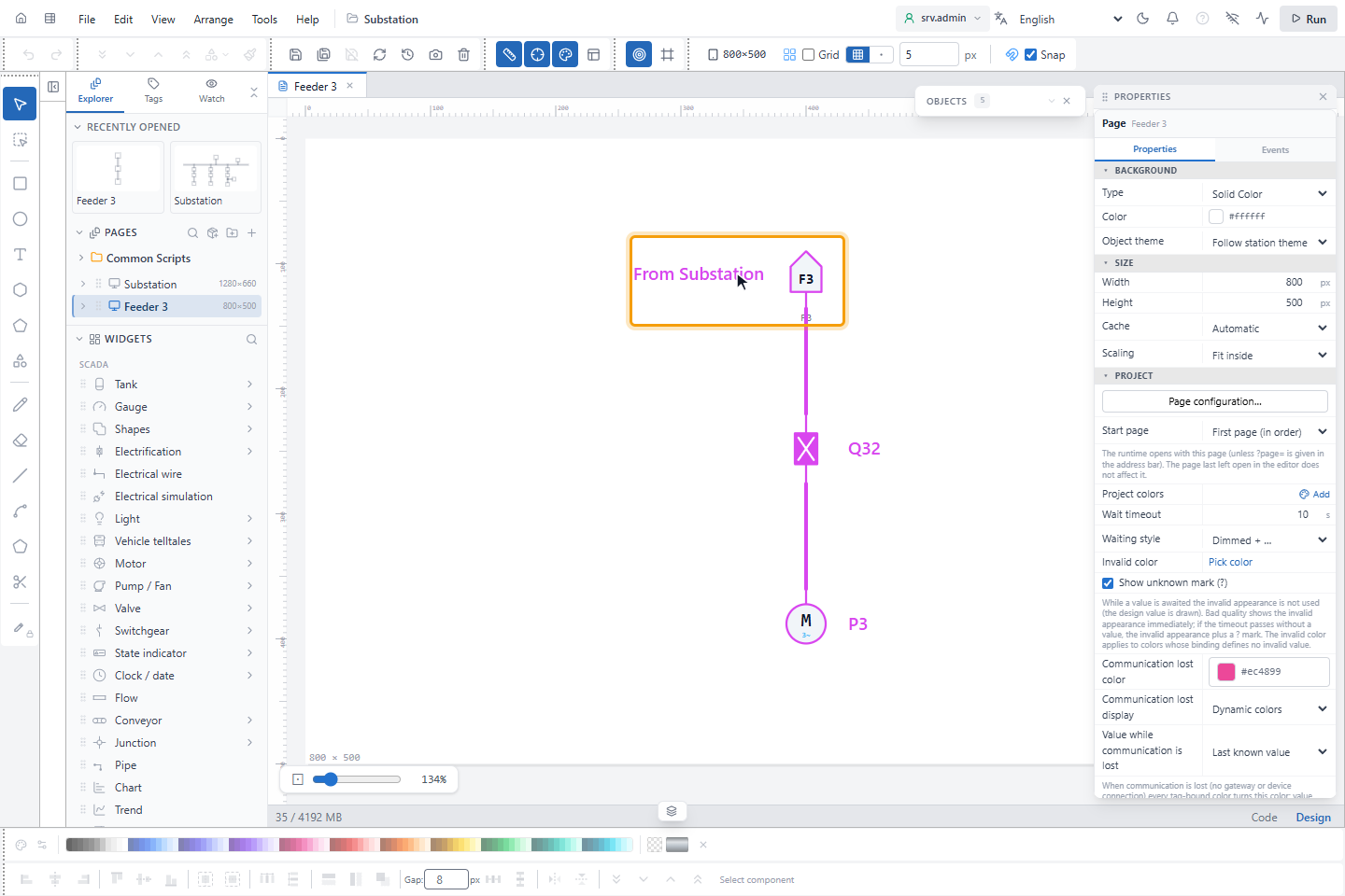
If more than two connectors have the same name, they are all joined. ELECTRICAL CHECK warns about a link name without a partner.
3. Go to the partner page on the run screen
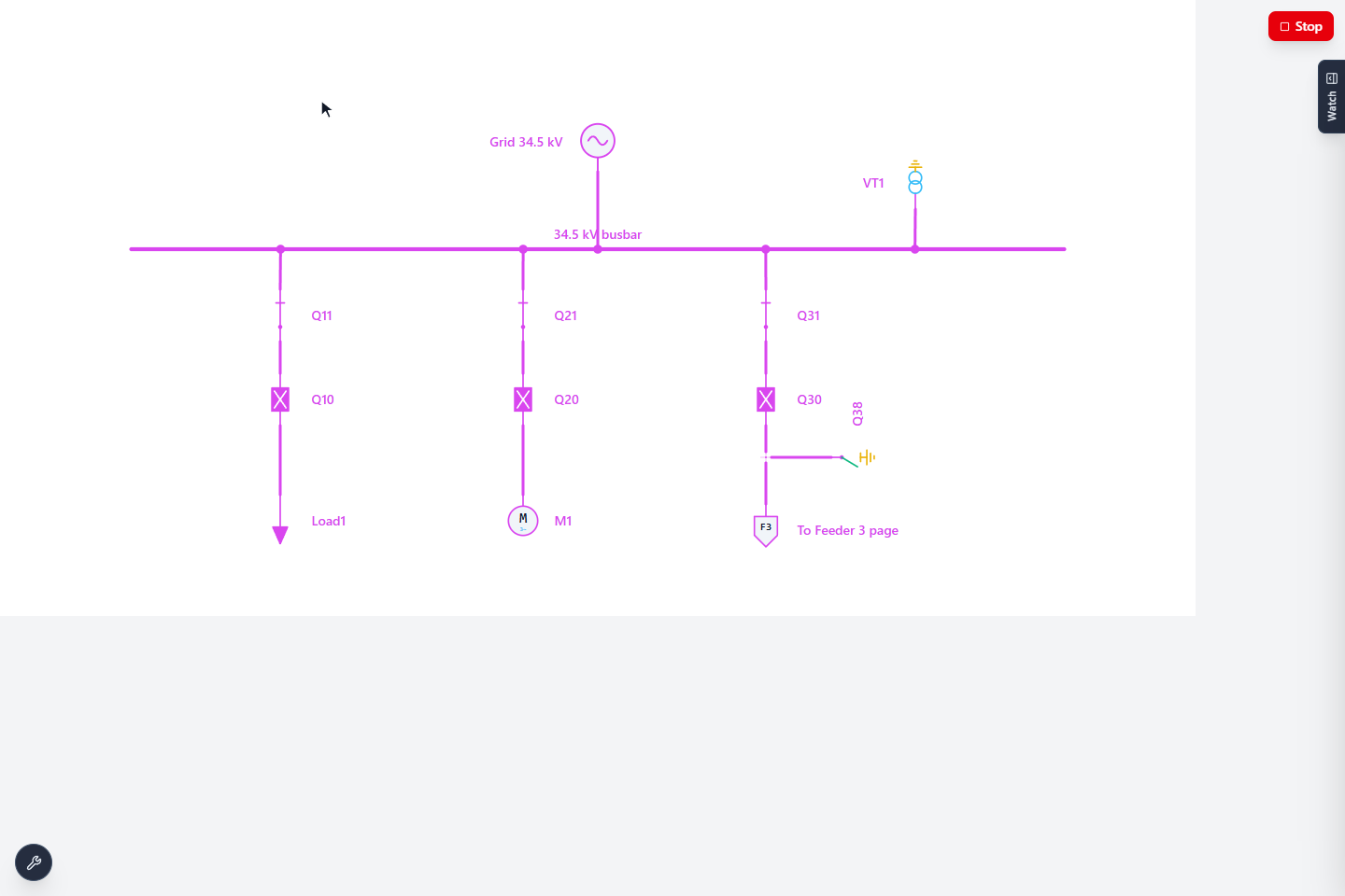
On the run screen, clicking a named connector opens the page of its partner. With several partners, the first one found is opened. A click action set on the connector by the designer replaces this.
Show the color of a device from another page
A detail page, for example the detail of one feeder, can show a device of the overview diagram in that device's live
color without drawing the network again. Select the electrical symbol or wire on the detail page and type the device in
Electrical › Color source (page/object) as <page id>/<object id>, for example overview/cb_12.
On the runtime screen the object then shows what the device shows on its own page: the energized state, the color of the source and the voltage level, definite or possible, and the marks such as communication lost, tripped, intermediate position and blinking. A symbol takes the colors of the sections at the device's terminals; a wire takes the color of the section at the device's first terminal. Leave the box empty to color the object from its own connections.
- The colors come from the topology service on the server, which runs only for a project with Electrification ticked. Until the first state arrives, and when the device is not in the project (deleted or renamed), the object keeps its design color.
- Only the page on the screen follows its color sources, and they are released when the page changes. A screen follows at most 256 devices on at most 32 source pages; above that the server refuses the whole set.
- Only devices of a project you may read can be followed.
- The screen editor shows the design color, also in the live preview and in Run.
Good to know
- A project symbol that contains electrical objects, for example a breaker with its load drawn as a feeder symbol, is part of the network with its position, size, rotation and mirroring. Instances whose symbol is chosen by a signal or a variant are not.
- The electrical simulation in the editor applies to the open page only.