Place symbols and draw wires
A single-line diagram is made of electrical symbols (sources, busbars, switches, transformers, loads) connected by electrical wires. YTCC follows the wires to color the diagram, so a wire must end on a terminal, a busbar or another wire; a wire that only looks connected is not.
Before you begin
- A page is open in the screen editor. See A tour of the screen editor.
- The project's Electrification module is on: click an empty place on the canvas and, in PROPERTIES under PROJECT, tick Modules › Electrification. A new project has it off; without it, WIDGETS has no Electrification, Electrical wire and Electrical simulation, and the server does not run the topology service. After changing it, save and restart the project.
Steps
1. Find a symbol
In WIDGETS, click Electrification. The symbol list opens with eight categories, from Switching & cells to
Control & auxiliary. Type in Search symbols… to filter: the search finds the name (upper and lower case and
Turkish letters do not matter), the ANSI number such as 52 or 89, the IEC 61850 logical node such as XCBR, the ISA
tag and the sector.
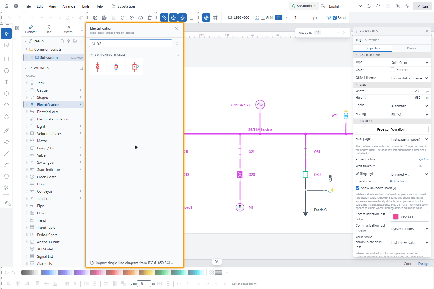
Hover over a symbol to see its name, its standard designations and a short description.
2. Place the symbol
Click the symbol and draw a rectangle on the page, or drag it onto the canvas. Symbols can be rotated and mirrored; their
labels stay readable. Give each symbol a short Label in PROPERTIES, for example Q10.
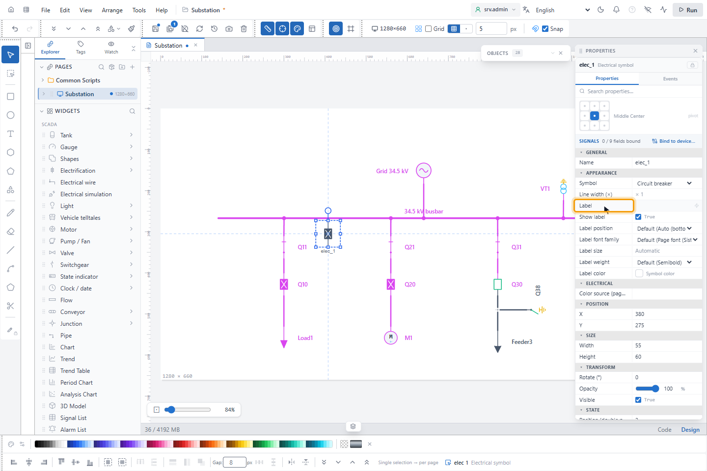
A Busbar is stretched to the length you need; its terminals run along its whole length, so wires can end anywhere on it.
3. Draw the wires
In WIDGETS, click Electrical wire, then:
- Click a symbol terminal, a busbar or another wire: the wire starts there. A snap mark shows the terminals nearby.
- Click empty places for corners. Hold Ctrl to draw horizontally or vertically, Shift for 45°.
- Click a terminal, a busbar or a wire to finish. Enter or a double-click also finishes, Esc cancels.
A wire that ends on another wire joins it with a T connection.
4. Change a wire
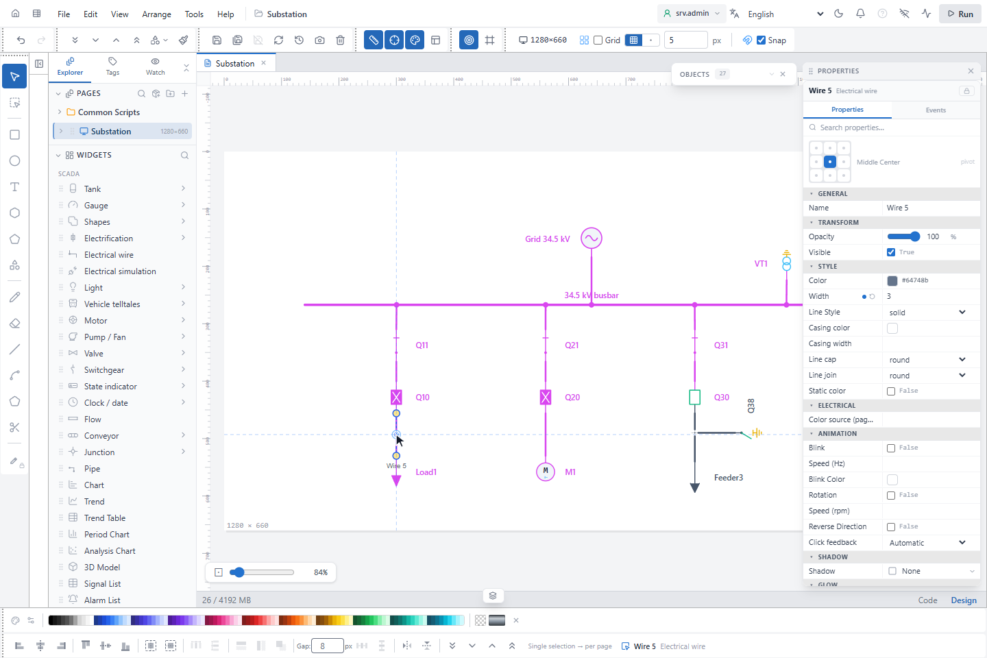
The ends of a wire follow the object they are bound to: move a symbol and its wires come with it. On a selected wire:
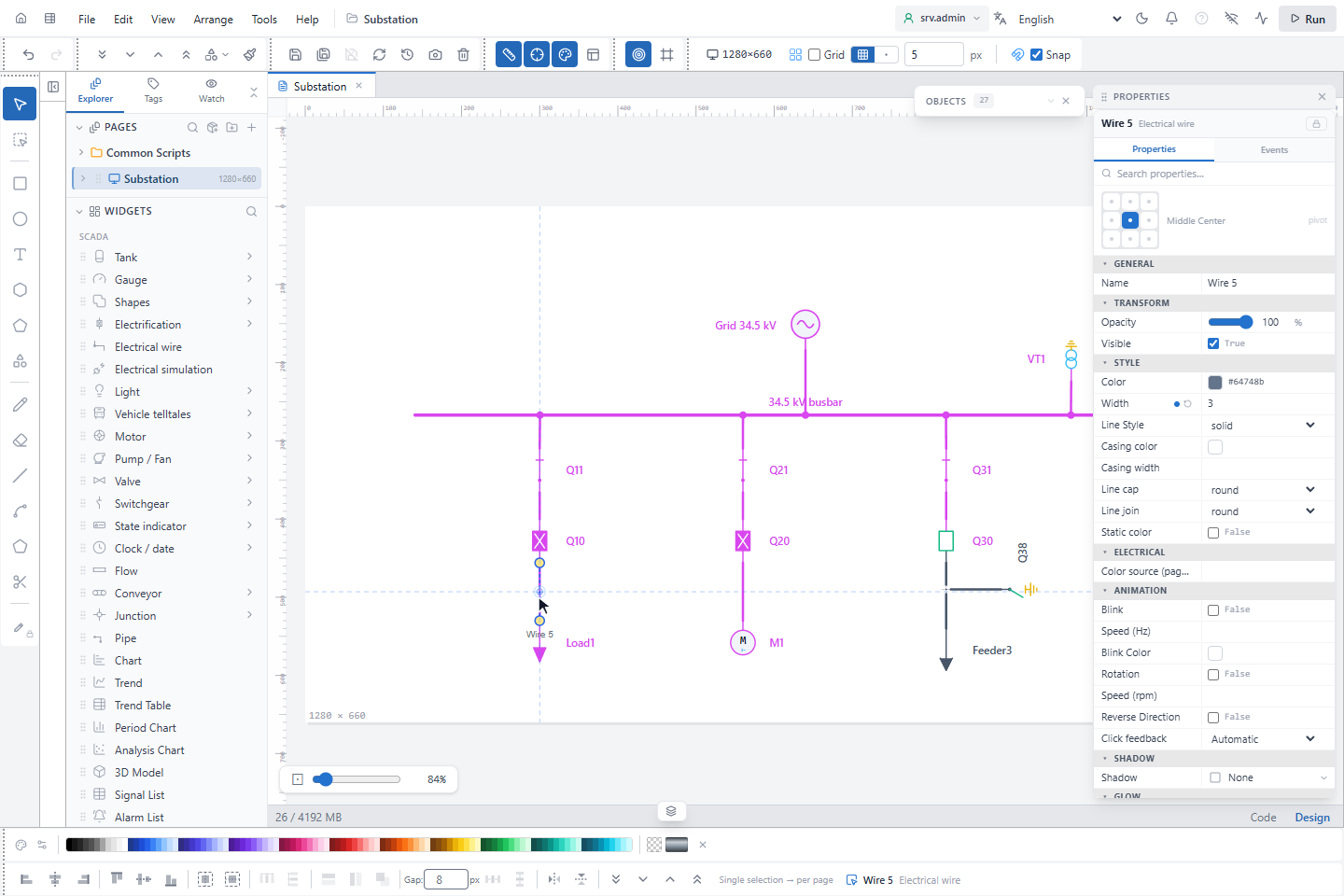
- drag a corner to move it; a bound end is shown in yellow;
- click + in the middle of a segment to add a corner; double-click a corner or press Delete to remove it;
- drag an end onto another terminal to connect it there.
5. Check the diagram
The ELECTRICAL CHECK section of the Explorer, shown for a page with electrical objects, lists the findings of the open page: errors (a source symbol without a source, an invalid user symbol), warnings (unconnected terminals, loose wire ends, areas no source can reach, off-page connectors without a partner) and information (a position not bound to a signal). Click a row to select the object.
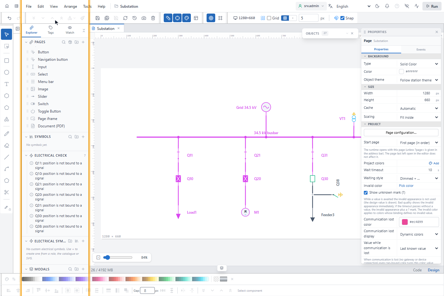
Fix the errors and warnings before you run the project; the information rows disappear as you bind the signals.
Result
The diagram is colored as soon as a source is set: see Voltage levels, sources and palette. Next, bind the switches and measurements to signals.