Add drivers and devices
YTCC talks to field equipment through drivers. Three levels make up the communication model:
| Level | What it is | Example |
|---|---|---|
| Driver | One communication process of a protocol | plc1, Modbus TCP |
| Device | A device that this process communicates with: its address and connection settings | plc1_main, host 192.168.1.10 |
| Address binding | The address in the device that gives a signal its value | holding register 40001 |
Each driver runs as a separate process. If one driver fails, the others go on working.
Before you begin
- The project is open in the configuration editor. See A tour of the configuration editor.
- You know the protocol, the address and the connection settings of the device.
Steps
1. Open the drivers view
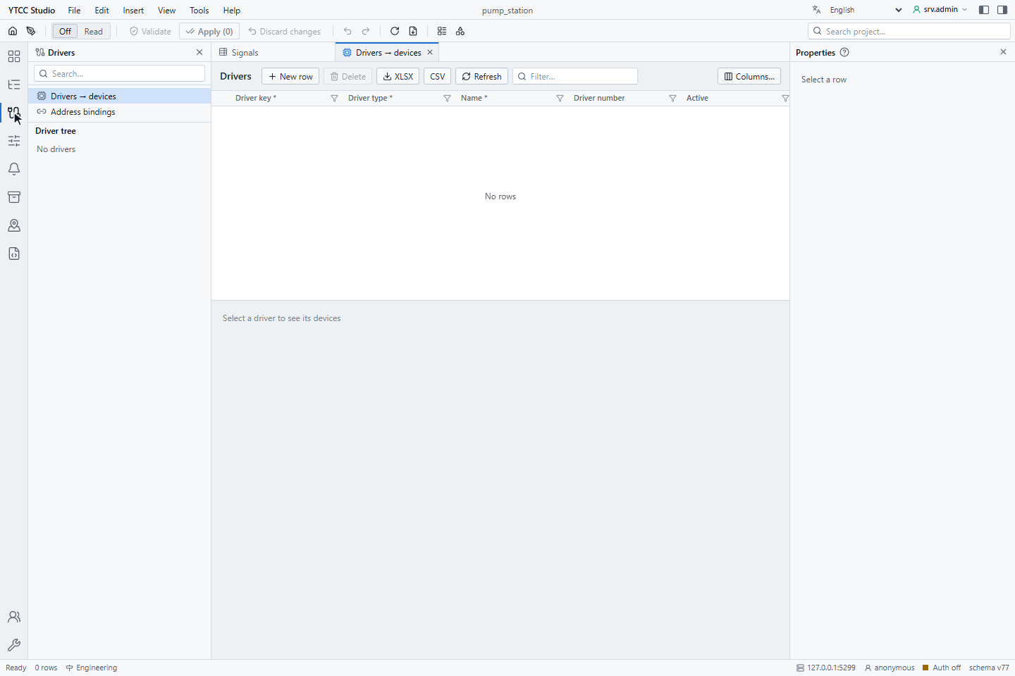
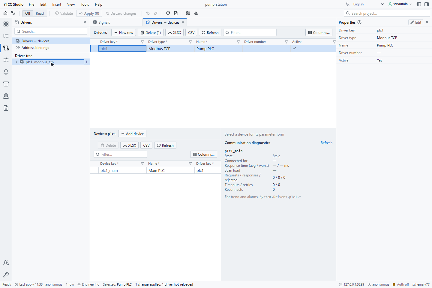
In the activity bar, click Drivers. The Drivers → devices view opens; Address bindings is the second view of this area. The Driver tree on the left lists the drivers and their devices, or No drivers.
2. Add a driver
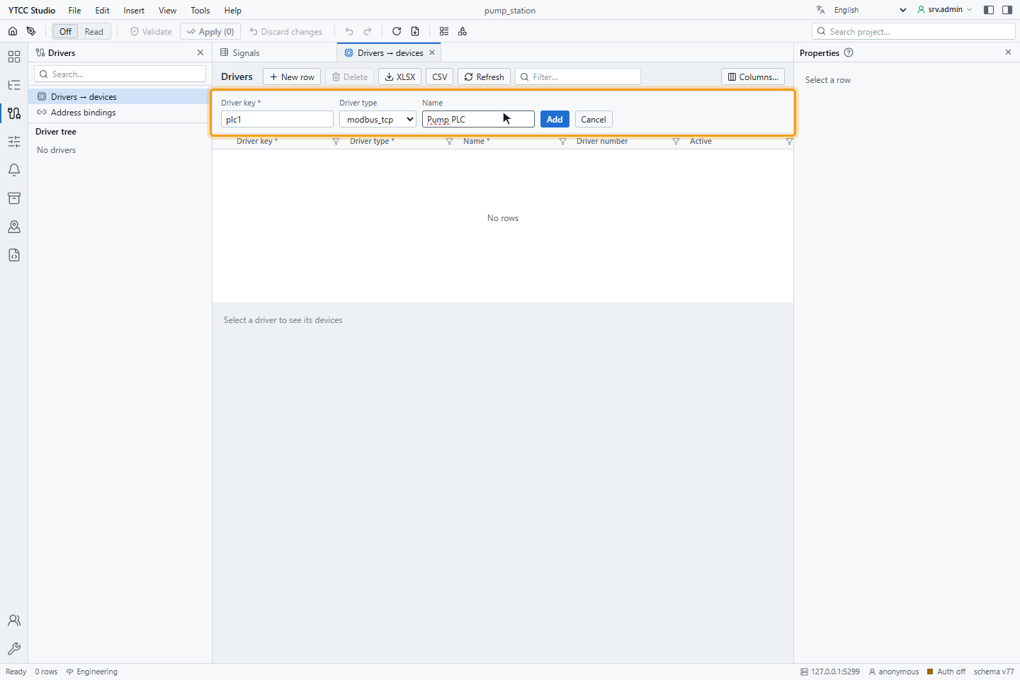
Click New row above the Drivers grid. Fill in:
- Driver key: the identity of the driver, for example
plc1. - Driver type: the protocol, here
modbus_tcp. - Name: a readable name, for example
Pump PLC.
Click Add. The row appears under New — not applied (1).
The OPC UA server and MQTT server drivers are server roles: YTCC itself serves data, and these drivers have no devices.
3. Apply the driver
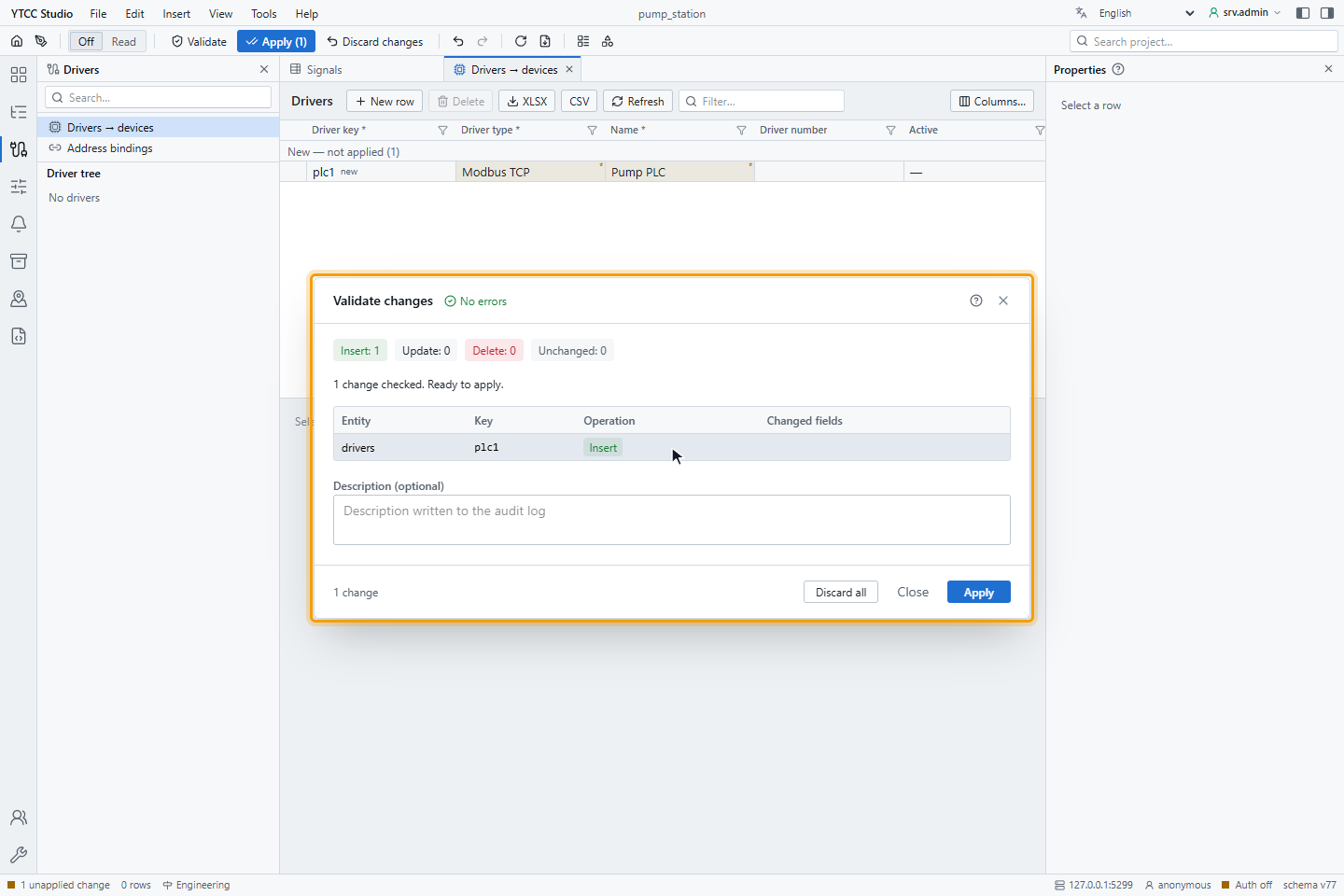
Click Apply (1) in the toolbar. Validate changes lists the new row of drivers; click Apply, then OK.
The driver now appears in the Driver tree.
Apply the driver before you add its devices. For a driver that is not applied yet, the device list shows a validation error instead of an empty list.
4. Add a device
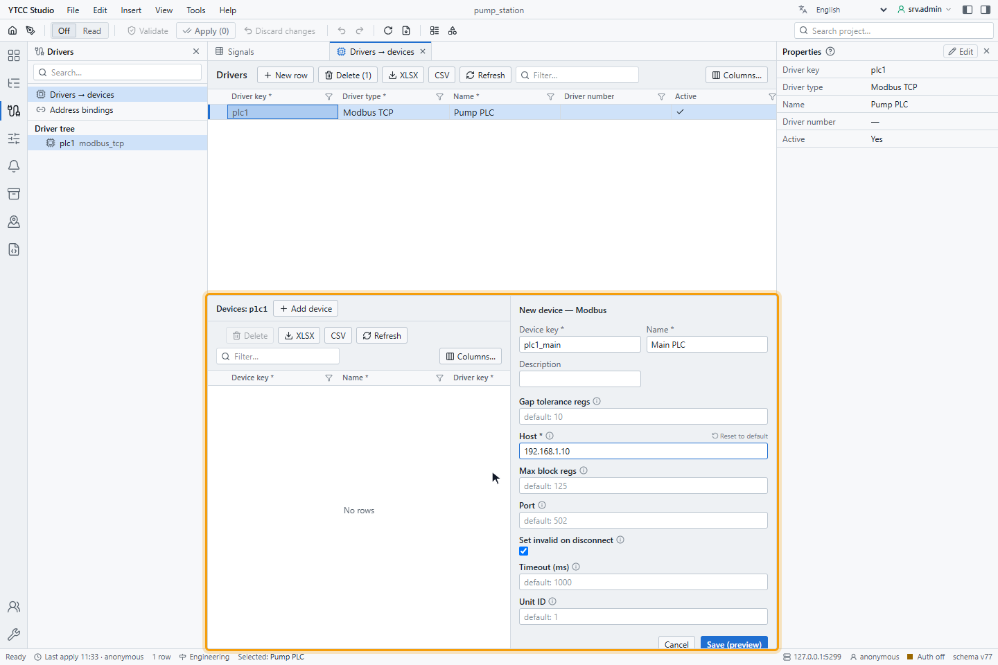
Select the driver in the grid. The lower part shows Devices: plc1. Click Add device. The form New device — Modbus opens on the right with:
- Device key and Name (required), and Description.
- The protocol's connection settings. For Modbus TCP: Host (required), Port (default 502), Unit ID (default 1), Timeout (ms) (default 1000), Max block regs (default 125), Gap tolerance regs (default 10) and Set invalid on disconnect (on by default). An empty box uses the default shown in it; the ⓘ icon explains each setting.
For the example, enter the device key plc1_main, the name Main PLC and the host 192.168.1.10.
5. Save and apply the device
Click Save (preview). Change preview lists the insert of plc1_main in equipments and, under Affected
drivers, plc1 — will hot-reload. Click Apply, then OK. The status bar reports 1 change applied; 1
driver hot-reloaded.
Result
The project has the driver plc1 with the device plc1_main. While the project runs, the driver connects to the device.
To give a signal its value from the device, choose the device and the address on the Value source tab of the signal;
see Create signals.
Check the communication of a device
While the project runs, the Communication diagnostics panel shows how well a device communicates. Select the device in the Driver tree: the panel is below its settings on the right. With a driver selected and no device, the panel lists all devices of the driver. It is refreshed every 3 seconds while it is open; Refresh reads it at once.
| Row | Meaning |
|---|---|
| State | Connected, Initial scan, Inactive or Not connected. Stale when the driver has not reported for more than 15 seconds; the other values are then old too. |
| Connected for | How long the device has been connected; — when it is not connected. |
| Response time (avg / worst) | Average and longest time from request to response in ms, since the device last connected. |
| Scan load | The scan cycle relative to its target, in %, with both times in ms. At 80 % or more it turns amber, at 100 % or more red: the device cannot be read as often as its signals ask for; see How often values are read. |
| Requests / responses / rejected | Frames sent, received and rejected. |
| Timeouts / retries | Responses that did not arrive in time, and requests sent again, since the driver process started. |
| Reconnects | Connections after the first one since the driver process started. |
| Last error | The last error reported by the driver, when there is one. |
A response time or scan load that the driver does not measure is shown as —; a counter that it does not measure
stays at 0. When the project is not running, the panel says No live
diagnostics: the project is not running or the gateway cannot be reached. The same values are system signals under
System.Drivers.<driver>.<device>, which you can put on a screen, in a trend or under an alarm; see
System, alarm and session signals.
The Modbus and IEC 60870-5-101 drivers measure the response time, Modbus, IEC 60870-5-101, BACnet/IP and DNP3 count the timeouts, IEC 60870-5-101, BACnet/IP and DNP3 count the retries, and Modbus measures the scan load. DNP3 counts the timeouts and retries of the link layer: every device of a channel shows the total of the channel since it last connected.
Good to know
- Hot reload. Most drivers load a changed configuration while they run: Affected drivers then says will hot-reload. If a driver must restart instead, it says requires a restart, and after Apply a strip appears: Drivers that must restart to load the new configuration: with a Restart button for each driver. Tools › Restart drivers does the same. The OPC UA server and MQTT server roles are restarted.
- Single-device protocols. SNMP, MQTT and IEC 61850 support one device per driver. After the first device, Add device is disabled: Single-device protocol — a second device cannot be added. Add another driver for the next device.
- Redundant reading. Normally a signal has one active source. To read the same signal from two devices, tick multi-source on the signal's Value source tab. Without it, a second binding is refused with Single-source rule: the point is already bound; enable multiple sources on the point for redundant reading.
- A driver can be made inactive with the Active column without deleting it.