Process signal values
A device often delivers a raw number, for example 0 to 10000 for a flow of 0 to 1000 m³/h. In the signal window you define how YTCC turns this into the value operators see, which values are valid, how jumpy values are steadied and how often the device is read. The settings are on the General and Value source tabs of the signal.
Before you begin
- The configuration editor is open and the signal exists. Open its window with a double-click on the row or with Enter. See Create signals.
Steps
1. Set the range and the scaling
On the General tab, enter the engineering range in Eng. Min and Eng. Max, here 0 to 1000, and the unit. Under Scaling choose how the raw value becomes the engineering value:
| Scaling | Fields | Engineering value |
|---|---|---|
| None | — | The raw value |
| Linear (raw → engineering) | Raw Min, Raw Max | Raw Min … Raw Max is mapped to Eng. Min … Eng. Max |
| Factor (raw × factor + offset) | Factor, Offset | raw × factor + offset |
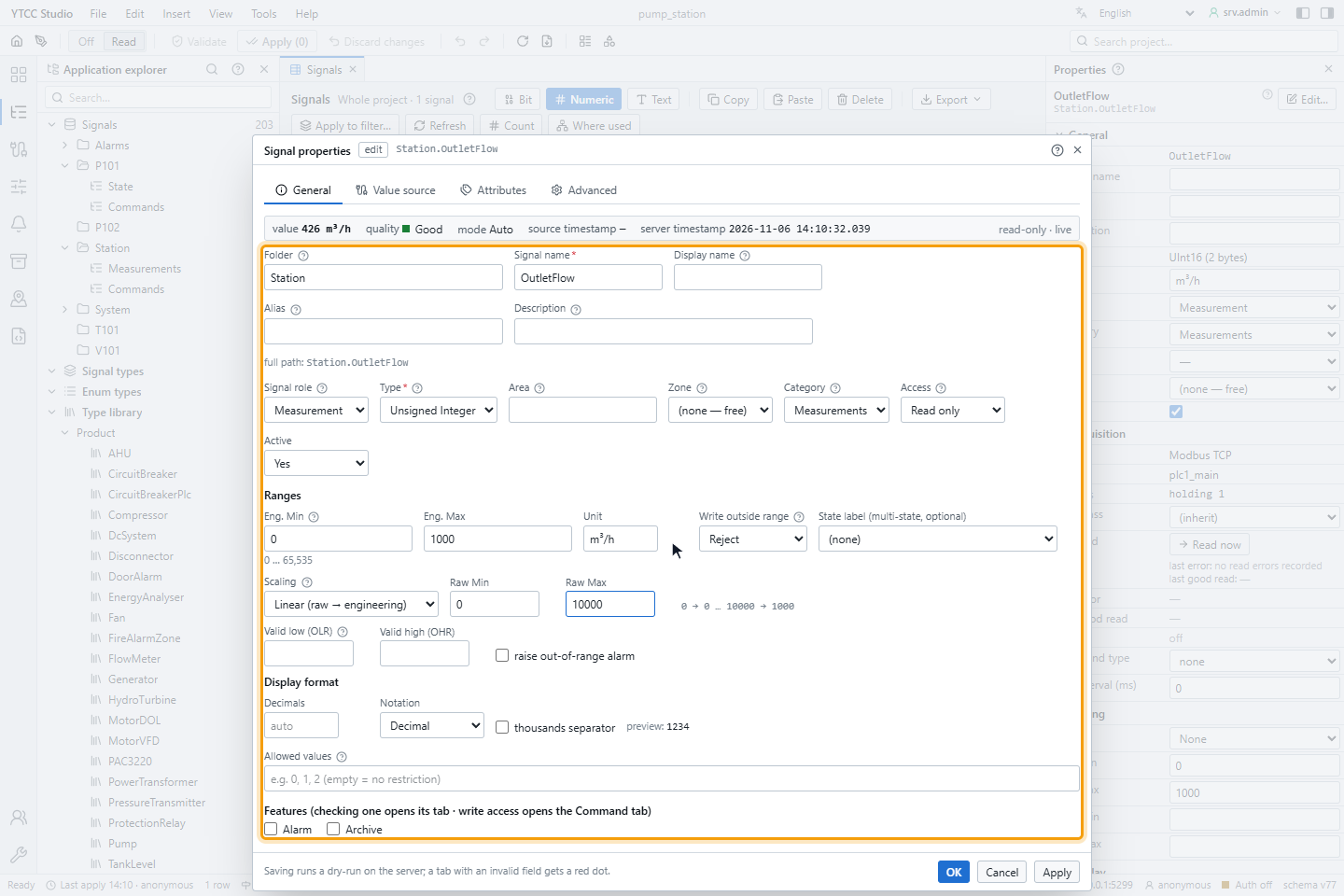
The line below the fields shows the result, here 0 → 0 … 10000 → 1000. Commands are converted back the same way before they are sent to the device.
Write outside range decides what happens when someone writes a value outside Eng. Min … Eng. Max: Reject (the default), Clamp to range (the operator confirms the clamped value) or Write + warn.
2. Set the valid range
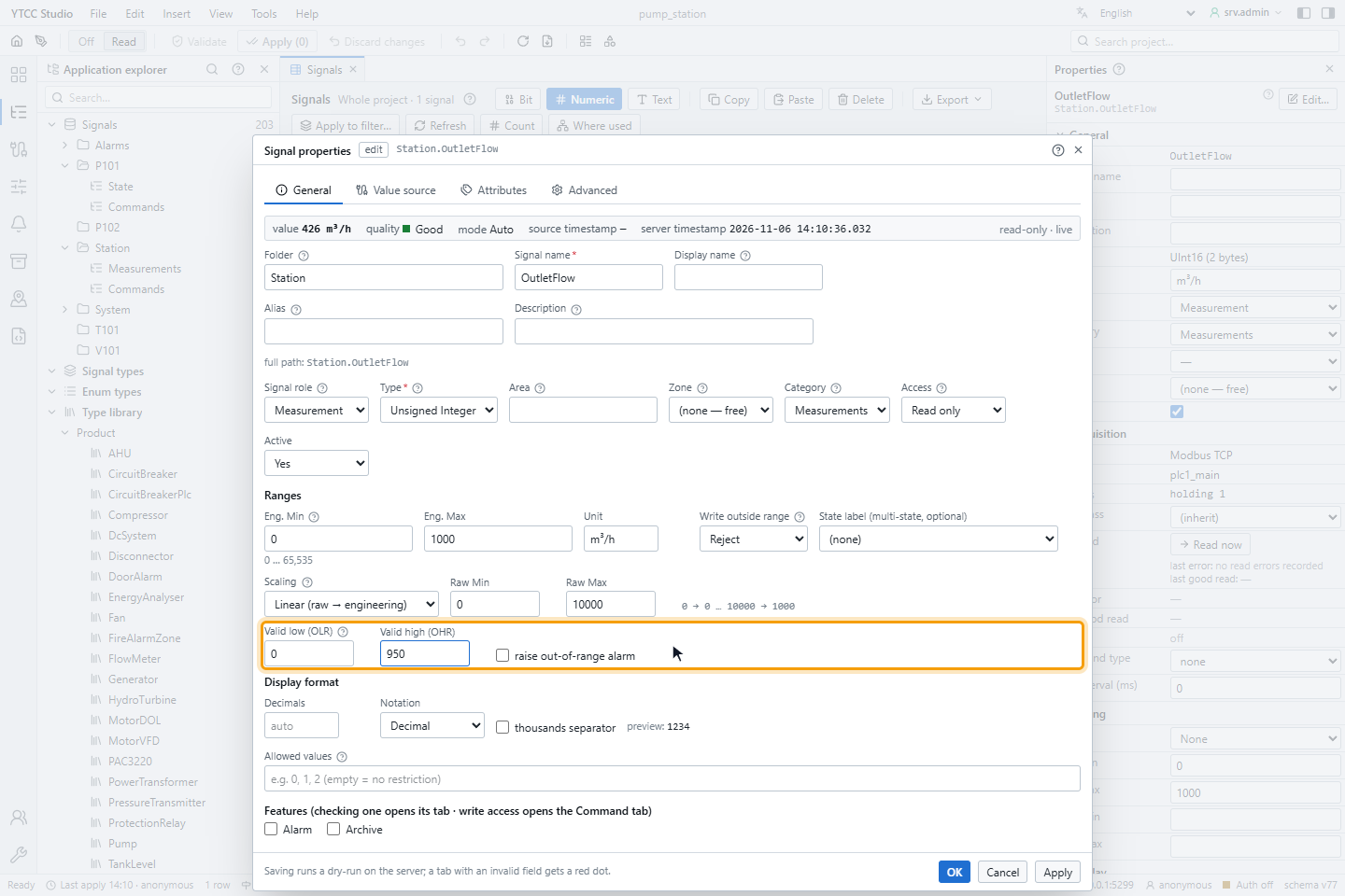
In Valid low (OLR) and Valid high (OHR) enter the values the measurement can really take, here 0 to 950. A value above or below is marked as over range or under range; its quality stays as it is.
For text signals the General tab offers Allowed values (for example AUTO,MANUAL,MAINT) and Max length
(characters) instead; a command with another text is refused.
3. Set filter and deadband
On the Value source tab, the Filter and deadband group steadies numeric values. All settings are off by default.
| Setting | Effect |
|---|---|
| Deadband (Absolute or % of span) and Deadband value | A new value is passed on only when it differs from the last one by more than this |
| Min interval (ms) | New values are passed on at most this often |
| Smoothing: Exponential damping with Time constant τ (s), or Moving average with Samples (2 to 100) | Smooths noise |
| The spike rejection box with Max change (… / s) and Accept after (samples) | Ignores jumps faster than the maximum change; a jump that lasts for the given number of samples (1 to 50) is accepted |
| Discard values | Values that mean "no measurement", for example 32767, -32768 (up to 32) |
| Outlier window (samples) and k (× MAD) | Ignores values far from the median of the last samples (window 3 to 200) |
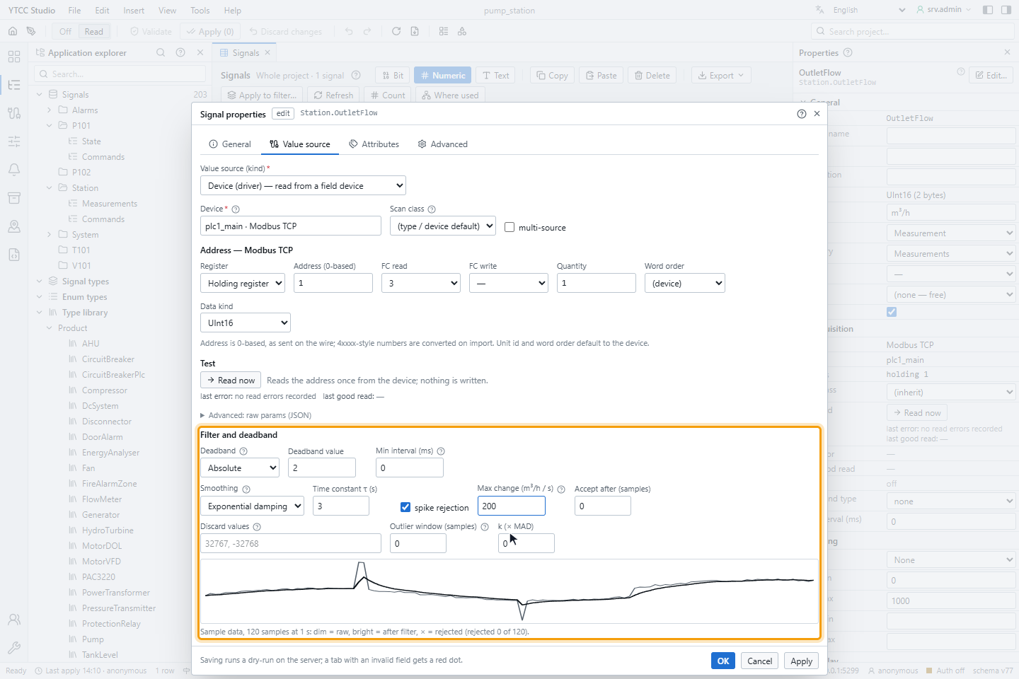
The chart shows the effect on 120 sample values: dim the raw values, bright the result, × the rejected values.
4. Choose the scan class
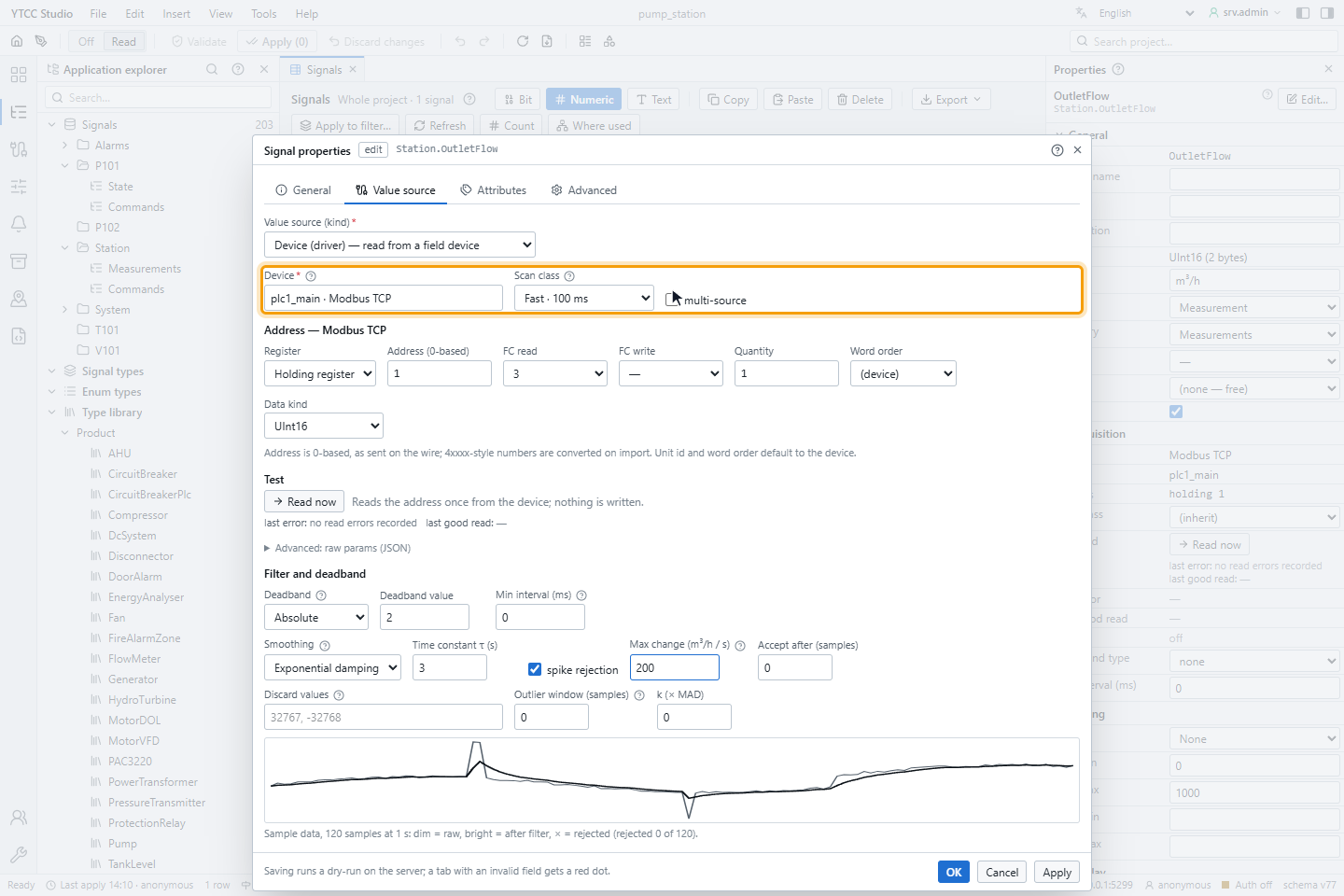
For signals read by polling (Modbus, S7, OPC UA, BACnet, SNMP, EtherNet/IP, ADS), Scan class sets how often the device is read:
| Scan class | Period |
|---|---|
| (type / device default) | The setting of the signal type, the device or the project |
| Fast | 100 ms |
| Normal | 1 s |
| Slow | 10 s |
| Background | 60 s |
| Custom… | 20 ms to 3 600 000 ms (1 hour); below 100 ms YTCC warns about device and network load |
Signals of event-driven protocols, such as IEC 104 or MQTT, are not polled and have no scan class.
Click OK and apply the configuration; see Validate and apply.
Order of processing
For each value read from the device YTCC applies the settings in this order:
- Scaling. A result that is not a finite number gets the quality Bad.
- Valid range check (only for values with good quality).
- Filter: discard values, outliers, spikes, then smoothing and min interval (only for good numeric values).
- Deadband: only a sufficient change is passed on to screens, alarms and history.
Internal signals have no scaling; filter and deadband apply to them in the same way.
Good to know
- Filter and deadband apply only to numeric signals. Values with a bad quality pass through unfiltered.
- A deadband in % of span is calculated from Eng. Min and Eng. Max.